2026年2月更新,Step to UEFI 文章索引:
PDF 转 Markdown 网站
这个网站可以帮助你把 pdf 转为 MarkDown格式,比较特别的是除了文字,它还能将PDF中的图片以 Base64 格式重新编码后插入在 MD 文件中:
对于MD文件,普通的记事本就可以打开,但是如果想看带有图片的MD, 可以使用下面这这个网站 :
做一个 UEFI 下的 EasyX 图形库(1)
之前我使用过一个 Windows 下的图形库:EasyX(官方网站https://easyx.cn/),它可以帮助用户非常方便的在Windows下实现简单的绘图功能,
美中不足的是这个库并非开源项目,因此无法直接进行迁移。
这次我尝试编写一个 UEFI 下的 EasyX 库,尽量做到完全兼容。代码主要是 AI 生成。
本来打算做成一个库,但是后来考虑到通俗易懂直接方便,索性直接和 Application 写在了一起。这样做更加直截了当,并且方便用户自行剪裁。
测试编写的UEFI Application假设所有内容处于\AppPkg\Applications\EasyXDemo1 目录下,然后在AppPkg\AppPkg.dsc中加入下面这一行:
AppPkg/Applications/EasyXDemo1/EasyXDemo.inf
代码如下:
/** @file
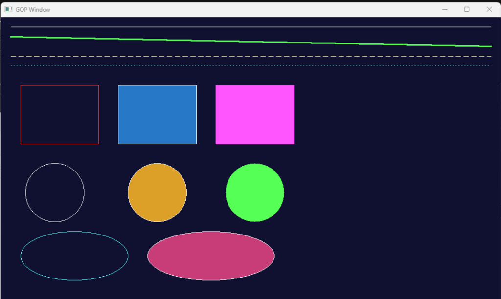
EasyX UEFI 图形库演示程序(阶段 P0 + P1)。
演示:初始化设备、清屏、绘制直线、矩形、圆、椭圆及其填充变体,
然后等待任意按键后退出。
**/
#include <Uefi.h>
#include <Library/UefiBootServicesTableLib.h>
#include <Library/UefiLib.h>
#include "easyx.h"
/**
等待用户按下任意键。
**/
STATIC
VOID
WaitAnyKey (
VOID
)
{
EFI_INPUT_KEY Key;
UINTN Index;
gBS->WaitForEvent (1, &gST->ConIn->WaitForKey, &Index);
gST->ConIn->ReadKeyStroke (gST->ConIn, &Key);
}
/**
程序入口。
**/
EFI_STATUS
EFIAPI
UefiMain (
IN EFI_HANDLE ImageHandle,
IN EFI_SYSTEM_TABLE *SystemTable
)
{
EFI_STATUS Status;
INT32 W;
INT32 H;
//
// 初始化绘图设备(跟随 GOP 最大分辨率模式)。
//
Status = initgraph (0, 0);
if (EFI_ERROR (Status)) {
Print (L"initgraph 失败: %r\n", Status);
return Status;
}
W = getwidth ();
H = getheight ();
//
// 批量绘图,减少刷新次数。
//
BeginBatchDraw ();
//
// 背景填充深蓝。
//
setbkcolor (RGB (16, 16, 48));
cleardevice ();
//
// 直线:不同颜色/线宽/线型。
//
setlinecolor (WHITE);
setlinestyle (PS_SOLID, 1);
line (20, 20, W - 20, 20);
setlinecolor (LIGHTGREEN);
setlinestyle (PS_SOLID, 3);
line (20, 40, W - 20, 60);
setlinecolor (YELLOW);
setlinestyle (PS_DASH, 1);
line (20, 80, W - 20, 80);
setlinecolor (LIGHTCYAN);
setlinestyle (PS_DOT, 1);
line (20, 100, W - 20, 100);
//
// 矩形。
//
setlinestyle (PS_SOLID, 1);
setlinecolor (LIGHTRED);
rectangle (40, 140, 200, 260);
setfillcolor (RGB (40, 120, 200));
setlinecolor (WHITE);
fillrectangle (240, 140, 400, 260);
setfillcolor (LIGHTMAGENTA);
solidrectangle (440, 140, 600, 260);
//
// 圆。
//
setlinecolor (WHITE);
circle (110, 360, 60);
setfillcolor (RGB (220, 160, 40));
setlinecolor (WHITE);
fillcircle (320, 360, 60);
setfillcolor (LIGHTGREEN);
solidcircle (520, 360, 60);
//
// 椭圆。
//
setlinecolor (LIGHTCYAN);
ellipse (40, 440, 260, 540);
setfillcolor (RGB (200, 60, 120));
setlinecolor (WHITE);
fillellipse (300, 440, 560, 540);
//
// 一次性刷新并结束批量绘图。
//
EndBatchDraw ();
//
// 等待按键后清理退出。
//
WaitAnyKey ();
closegraph ();
//
// 恢复文本控制台。
//
gST->ConOut->ClearScreen (gST->ConOut);
Print (L"EasyX UEFI Demo 结束。分辨率: %d x %d\n", W, H);
return EFI_SUCCESS;
}
在EDK2 自带的模拟器中测试结果如下,可以说完全达到了预期:
完整代码和编译后的 EFI 可以在这里下载:
Ch32V307 I2C 扫描程序
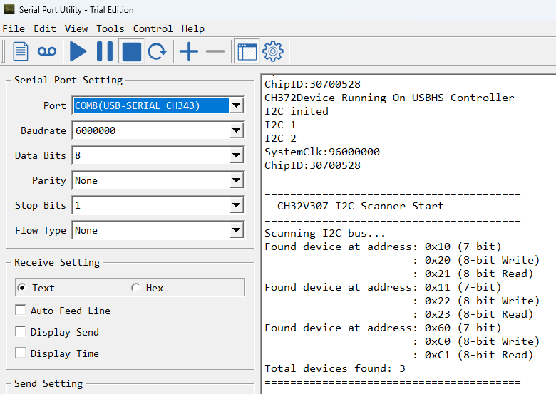
Ch32V307 使用 I2C2 进行扫描的代码,使用 I2C2 ,对应引脚 PB10 为 SCL , PB11 为 SDA。串口输出波特率 6000 000bps。
#include “ch32v30x.h”
#include “debug.h”
/* I2C 引脚定义 (可根据实际硬件修改) */
#define I2C_SCL_PIN GPIO_Pin_10
#define I2C_SDA_PIN GPIO_Pin_11
#define I2C_PORT GPIOB
#define I2C_CLK RCC_APB2Periph_GPIOB
/* I2C 实例定义 */
#define I2C_INSTANCE I2C2
#define I2C_CLK_SRC RCC_APB1Periph_I2C2
/* I2C GPIO 初始化 */
void I2C_GPIO_Init(void)
{
GPIO_InitTypeDef GPIO_InitStructure;
RCC_APB2PeriphClockCmd(I2C_CLK, ENABLE);
GPIO_InitStructure.GPIO_Pin = I2C_SCL_PIN | I2C_SDA_PIN;
GPIO_InitStructure.GPIO_Speed = GPIO_Speed_50MHz;
GPIO_InitStructure.GPIO_Mode = GPIO_Mode_AF_OD; // 开漏复用输出
GPIO_Init(I2C_PORT, &GPIO_InitStructure);
}
/* I2C 模块初始化 */
void I2C_Master_Init(void)
{
I2C_InitTypeDef I2C_InitStructure;
RCC_APB1PeriphClockCmd(I2C_CLK_SRC, ENABLE);
I2C_DeInit(I2C_INSTANCE);
I2C_InitStructure.I2C_ClockSpeed = 100000; // 100kHz 标准模式
I2C_InitStructure.I2C_Mode = I2C_Mode_I2C;
I2C_InitStructure.I2C_DutyCycle = I2C_DutyCycle_2;
I2C_InitStructure.I2C_OwnAddress1 = 0x00; // 主机模式不需要自身地址
I2C_InitStructure.I2C_Ack = I2C_Ack_Enable;
I2C_InitStructure.I2C_AcknowledgedAddress = I2C_AcknowledgedAddress_7bit;
I2C_Init(I2C_INSTANCE, &I2C_InitStructure);
I2C_Cmd(I2C_INSTANCE, ENABLE);
}
/* 检测单个 I2C 地址是否存在设备 */
// 返回 0: 设备存在 (ACK), 1: 无设备 (NACK) 或错误
uint8_t I2C_Check_Device(uint8_t address)
{
I2C_GenerateSTART(I2C_INSTANCE, ENABLE);
// 等待起始条件发送完成
while(!I2C_CheckEvent(I2C_INSTANCE, I2C_EVENT_MASTER_MODE_SELECT));
// 发送地址 (写方向, 最后一位为0)
I2C_Send7bitAddress(I2C_INSTANCE, address << 1, I2C_Direction_Transmitter);
// 等待地址发送完成或接收到 NACK
// 注意:CH32V307 库函数可能需要根据具体状态标志判断
// 这里使用简单的超时机制和状态检查
uint32_t timeout = 10000;
while(timeout–)
{
if(I2C_GetFlagStatus(I2C_INSTANCE, I2C_FLAG_ADDR))
{
// 地址发送成功,收到 ACK
I2C_ClearFlag(I2C_INSTANCE, I2C_FLAG_ADDR);
I2C_GenerateSTOP(I2C_INSTANCE, ENABLE);
return 0; // 设备存在
}
if(I2C_GetFlagStatus(I2C_INSTANCE, I2C_FLAG_AF))
{
// 收到 NACK
I2C_ClearFlag(I2C_INSTANCE, I2C_FLAG_AF);
I2C_GenerateSTOP(I2C_INSTANCE, ENABLE);
return 1; // 无设备
}
}
// 超时错误
I2C_GenerateSTOP(I2C_INSTANCE, ENABLE);
return 1;
}
/* 扫描总线上的所有设备 */
void I2C_Scan_Bus(void)
{
uint8_t address;
uint8_t found_count = 0;
printf(“\r\n========================================\r\n”);
printf(” CH32V307 I2C Scanner Start\r\n”);
printf(“========================================\r\n”);
printf(“Scanning I2C bus…\r\n”);
for(address = 1; address < 127; address++)
{
// 跳过保留地址 (通常 0x00 是通用呼叫,0x78-0x7F 是保留)
// 但为了全面扫描,我们扫描 1-127,具体保留地址视情况而定
if(I2C_Check_Device(address) == 0)
{
printf(“Found device at address: 0x%02X (7-bit)\r\n”, address);
printf(” : 0x%02X (8-bit Write)\r\n”, address << 1);
printf(” : 0x%02X (8-bit Read)\r\n”, (address << 1) | 1);
found_count++;
}
// 短暂延时,避免总线过于繁忙
Delay_Ms(5);
}
if(found_count == 0)
{
printf(“No I2C devices found.\r\n”);
}
else
{
printf(“Total devices found: %d\r\n”, found_count);
}
printf(“========================================\r\n\r\n”);
}
/*********************************************************************
* @fn main
*
* @brief Main program.
*
* @return none
*/
int main(void) {
SystemCoreClockUpdate();
Delay_Init();
USART_Printf_Init(6000000);
printf(“SystemClk:%d\r\n”, SystemCoreClock);
printf(“ChipID:%08x\r\n”, DBGMCU_GetCHIPID());
I2C_GPIO_Init();
I2C_Master_Init();
while(1)
{
I2C_Scan_Bus();
Delay_Ms(5000); // 每5秒扫描一次
}
}
运行结果:
UEFI EDK2 INF 文件编码问题
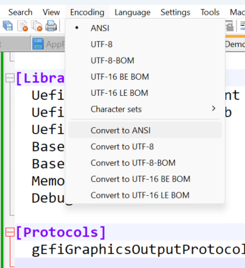
最近偶然发现,如果EDK2 INF使用 Unicode 编码,可能会导致“: error 0004: File read failure”错误。
例如:
Build environment: Windows-10-10.0.26100-SP0
Build start time: 10:58:15, Jul.16 2026

WORKSPACE = c:\buildbs\edk2202302\edk2
EDK_TOOLS_PATH = c:\buildbs\edk2202302\edk2\basetools
EDK_TOOLS_BIN = c:\buildbs\edk2202302\edk2\basetools\bin\win32
CONF_PATH = c:\buildbs\edk2202302\edk2\conf
PYTHON_COMMAND = py -3

Processing meta-data .Architecture(s) = X64
Build target = DEBUG
Toolchain = VS2019

Active Platform = c:\buildbs\edk2202302\edk2\AppPkg\AppPkg.dsc

build.py…
: error 0004: File read failure
解决方法上来说,可以使用 Notepad++ 或者类似工具,更改一下编码,然后保存即可:
USB 3.0 U盘速度慢的一种可能
如果你的3.0U盘支持的是 BOT mode,那么很可能传输速度较慢。
判断的方法是查看描述符中的 Interface Protocol,如果是50h,那么就是。比如,下面来自我手上的一个U盘:
[Port13]  :  USB Mass Storage Device


Is Port User Connectable:         yes
Is Port Debug Capable:            yes
Companion Port Number:            3
Companion Hub Symbolic Link Name: USB#ROOT_HUB30#4&16cc2fc5&0&0#{f18a0e88-c30c-11d0-8815-00a0c906bed8}
Protocols Supported:
 USB 1.1:                         no
 USB 2.0:                         no
 USB 3.0:                         yes

Device Power State:               PowerDeviceD0

       ---===>Device Information<===---
English product name: "Disk 20"

ConnectionStatus:
Current Config Value:              0x01  -> Device Bus Speed: SuperSpeed
Device Address:                    0x17
Open Pipes:                           2

          ===>Device Descriptor<===
bLength:                           0x12
bDescriptorType:                   0x01
bcdUSB:                          0x0320
bDeviceClass:                      0x00  -> This is an Interface Class Defined Device
bDeviceSubClass:                   0x00
bDeviceProtocol:                   0x00
bMaxPacketSize0:                   0x09 = (9) Bytes
idVendor:                        0x346D = Vendor ID not listed with USB.org
idProduct:                       0x5678
bcdDevice:                       0x0200
iManufacturer:                     0x01
     English (United States)  "USB"
iProduct:                          0x02
     English (United States)  "Disk 20"
iSerialNumber:                     0x03
     English (United States)  "FC097CCF38A2A"
bNumConfigurations:                0x01

          ---===>Open Pipes<===---

          ===>Endpoint Descriptor<===
bLength:                           0x07
bDescriptorType:                   0x05
bEndpointAddress:                  0x01  -> Direction: OUT - EndpointID: 1
bmAttributes:                      0x02  -> Bulk Transfer Type
wMaxPacketSize:                  0x0400
bInterval:                         0x00

          ===>Endpoint Descriptor<===
bLength:                           0x07
bDescriptorType:                   0x05
bEndpointAddress:                  0x81  -> Direction: IN - EndpointID: 1
bmAttributes:                      0x02  -> Bulk Transfer Type
wMaxPacketSize:                  0x0400
bInterval:                         0x00

       ---===>Full Configuration Descriptor<===---

          ===>Configuration Descriptor<===
bLength:                           0x09
bDescriptorType:                   0x02
wTotalLength:                    0x002C  -> Validated
bNumInterfaces:                    0x01
bConfigurationValue:               0x01
iConfiguration:                    0x00
bmAttributes:                      0x80  -> Bus Powered
MaxPower:                          0x12 = 144 mA

          ===>Interface Descriptor<===
bLength:                           0x09
bDescriptorType:                   0x04
bInterfaceNumber:                  0x00
bAlternateSetting:                 0x00
bNumEndpoints:                     0x02
bInterfaceClass:                   0x08  -> This is a Mass Storage USB Device Interface Class
bInterfaceSubClass:                0x06
bInterfaceProtocol:                0x50
iInterface:                        0x00
如果使用抓包工具,会看到下面这种模式的传输
31B OUT
大块 IN
13B IN
与之相反,还有一种UASP,对应的Interface Protocol 是 62h,速度更快。
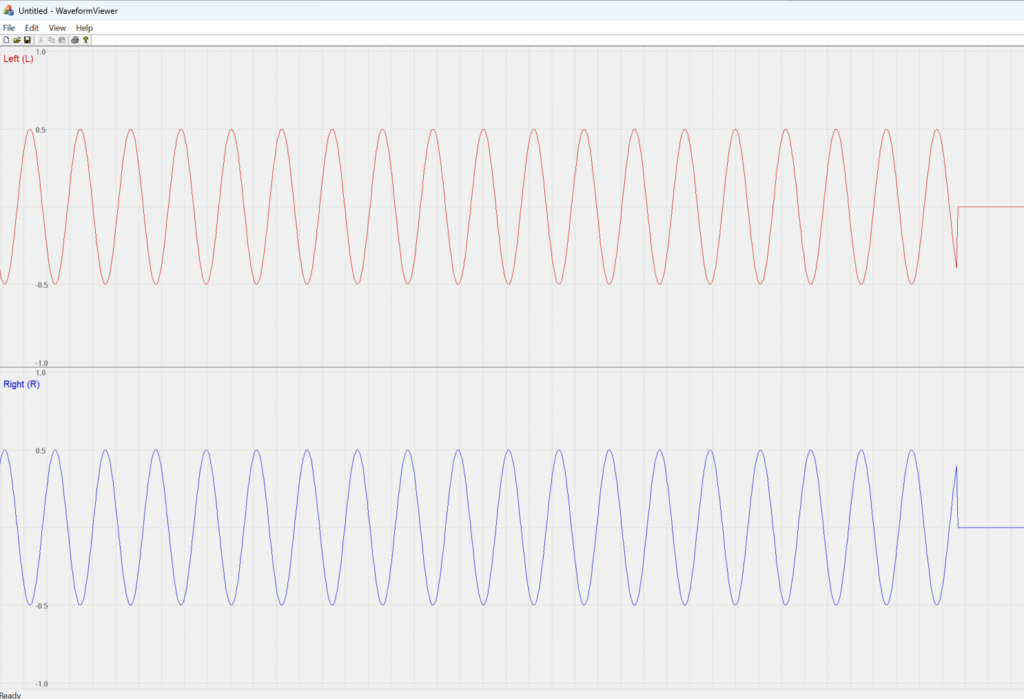
WAVE 音频文件查看器
吹蟑螂游戏机
这是一个使用表压传感器NSPGD1M006DT04设计一个双人对战的“吹蟑螂游戏机”。
在神秘的南亚次大陆,存在着一个神奇的国度,那里的人们经过几千年的洗礼,能够做到和各种小动物和平共存。在当地有着一个古老的游戏:吹蟑螂比赛。双方选手将一直蟑螂放置在玻璃管中,然后同时吹气,能够将蟑螂吹到另外一方的选手就获得了胜利。

很多人第一次听到这种游戏的时候,都会由衷感叹:印吹死挺!
项目描述
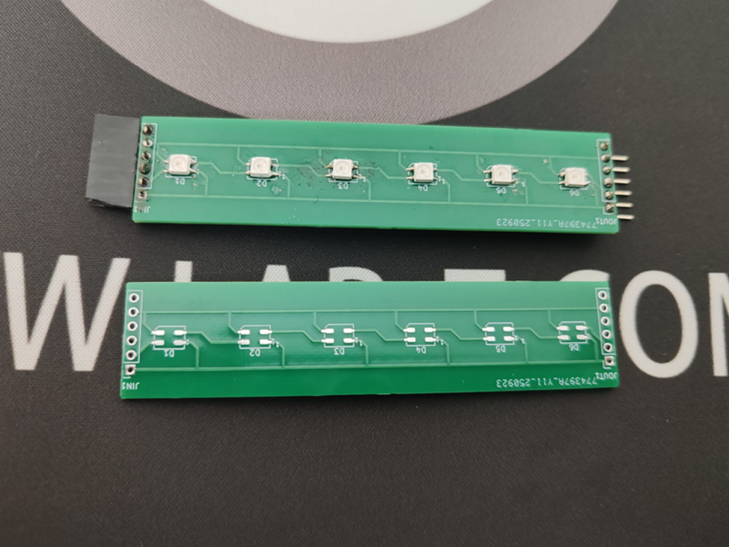
项目使用 WS2812 LED 作为指示灯,它是一款集控制电路与发光电路于一体的智能外控LED光源,其外型与5050LED灯珠相同,每个元件即为一个像素点。它采用单线归零码通信方式,通过一根信号线即可实现数据的接收与解码,支持级联控制,理论上可无限扩展。
游戏方法非常简单:
1. 双方比赛开始后,对着自己面前带有传感器的盒子吹气
2. 中间有24个LED,其中2个LED会亮起红色,当一方吹气后,LED会向着对方方向移动
3. 红色LED触及一方最后一个 LED后游戏结束
4. 按下按钮会重新开始新的对战
芯片选型/简短的硬件介绍
项目实际上有三块 PCB
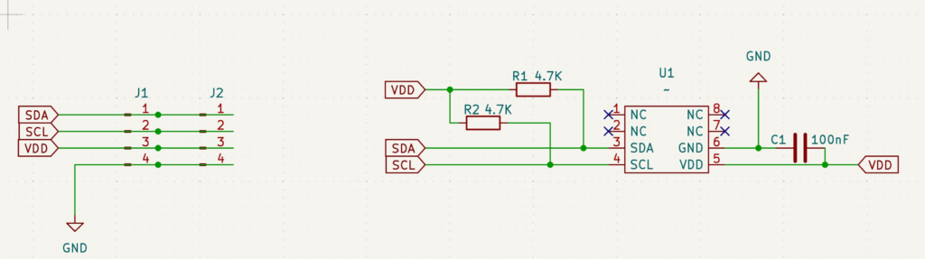
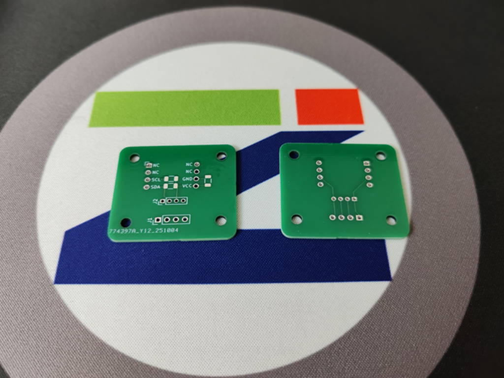
1. NSPGD1M006DT04 的转接板,方便我们实现这个传感器和 Arduino 的连接。NSPGD1M006DT04是表压传感器。表压传感器(Gauge Pressure Sensor)是一种测量相对压力的传感器,即相对于大气压力的压力值。相对的还有绝压传感器(Absolute Pressure Sensor)是一种测量相对于真空或绝对零点的压力的传感器。
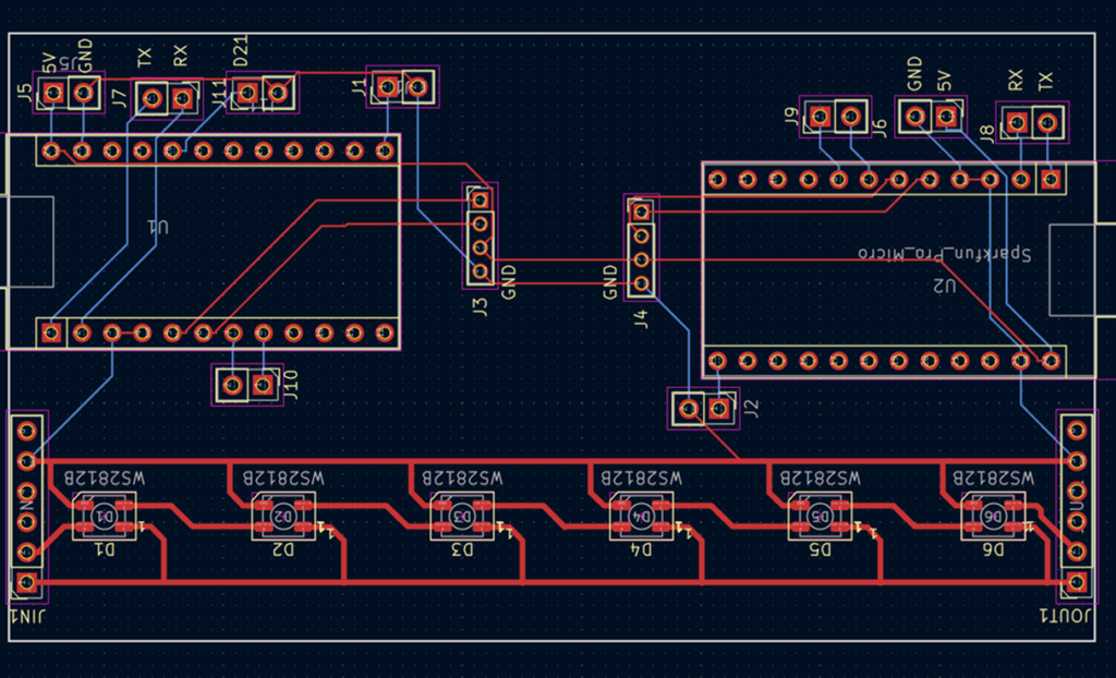
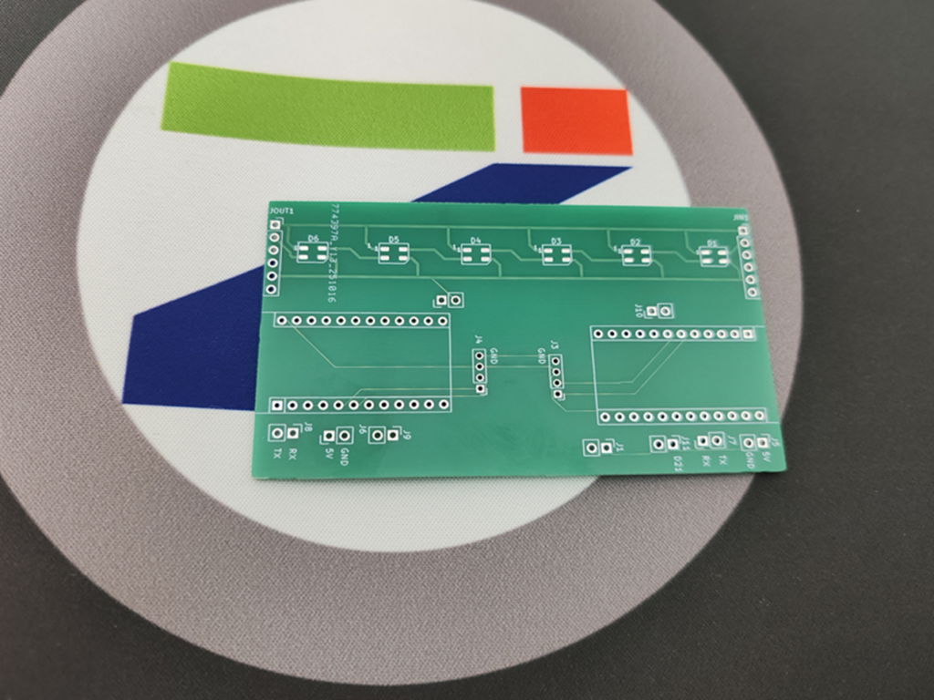
2. 带有 Arduino 的控制板,位于游戏机的最左侧和最右侧,理论上需要设计一个左侧和右侧板,但是这里为了成本考量,将二者放在同一块板子上,根据需要焊接左侧或者右侧;
3. WS2812 灯板,这个位于中间
出于成本考虑,板子长度都是小于10cm的,中间使用 U形状的 2.54mm排针进行连接
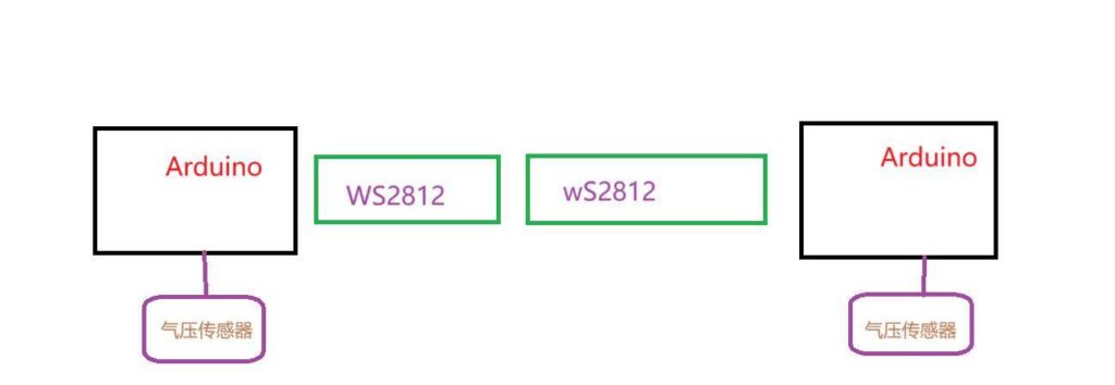
方案框图 + 设计思路
原理图、PCB设计
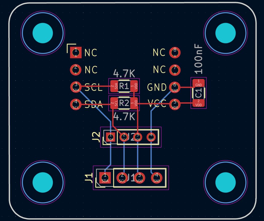
1.NSPGD1M006DT04 的转接板电路板和PCB
2.控制板电路和PCB设计,控制板上也带有 WS2812 LED,这样可以最大化利用空间
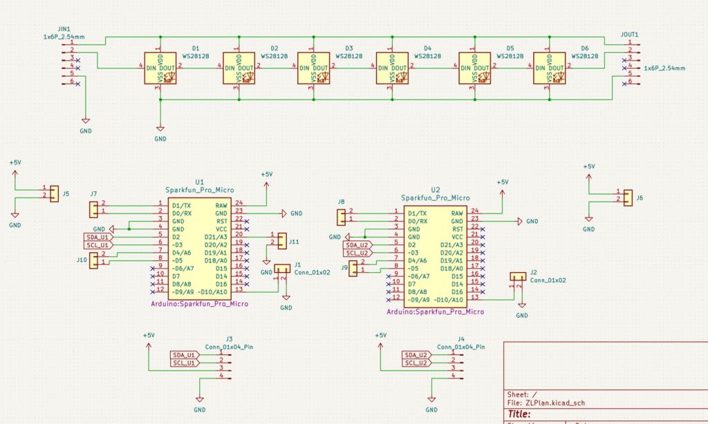
具体使用的时候,需要额外导线将右侧Arduino 的 TX 连接左侧的 RX
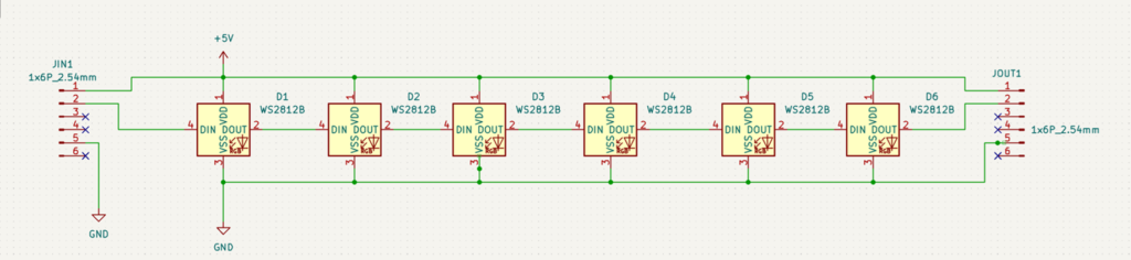
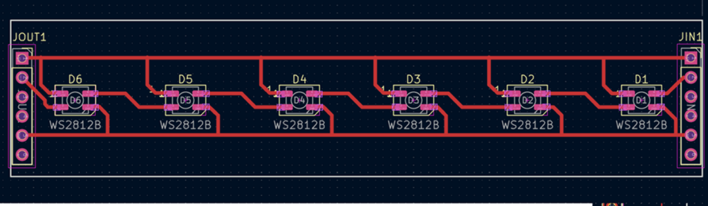
3.WS2812 电路板和 PCB,输入VCC ,控制信号(DIN)和 GND 即可,多余的引脚主要是为了保证连接的稳固
软件流程图 + 调试软件说明 + 关键代码说明
代码分为2部分:左侧和右侧 Arduino 代码不同(具体左右区分方法在下图中)。右侧的只负责读取传感器数据,然后通过串口传输给左侧。然后左侧同样获得传感器数据,比较之后对 WS2812 发送控制信号,操作LED
右侧代码:
#include <Wire.h>
#include "NSPGD1M006DT04.h"
NSPGD1M006DT04 sensor(0xFF);
void setup() {
Serial.begin(115200);
Serial1.begin(2400);
if (!sensor.begin()) {
Serial.println("Device not found");
while(1);
}
}
void loop() {
char s[20];
float pr=sensor.readPressure();
//float pr=3.14159269;
uint8_t *p;
dtostrf(pr,1,6,s);
Serial.println(s);
p=(uint8_t*)≺
Serial1.write(0x55);
Serial1.write(0xAA);
Serial1.write(*p);
Serial1.write(*(p+1));
Serial1.write(*(p+2));
Serial1.write(*(p+3));
delay(50);
}
左侧代码:
#include <FastLED.h>

#include "NSPGD1M006DT04.h"


// 灯带

#define LED_PIN     5

#define COLOR_ORDER GRB

#define CHIPSET     WS2812B

#define NUM_LEDS    24


#define BLOWTIME    300


#define RSTARTPIN   10


NSPGD1M006DT04 sensor(0xFF);


CRGB leds[NUM_LEDS];


void(* resetFunc) (void) = 0;


void setup() {

  //Serial.begin(115200);

  Serial1.begin(2400);

  if (!sensor.begin()) {

    Serial.println("Device not found");

    while (1);

  }


  pinMode(RSTARTPIN, INPUT_PULLUP);


  FastLED.addLeds<CHIPSET, LED_PIN, COLOR_ORDER>(leds, NUM_LEDS).setCorrection( TypicalLEDStrip );

  FastLED.setBrightness( 1 );


  for (uint8_t i = 0; i < NUM_LEDS / 2; i++) {

    memset(leds, 0, sizeof(leds));

    leds[NUM_LEDS / 2 - i] = CRGB::Red;

    leds[NUM_LEDS / 2 + i] = CRGB::Red;

    FastLED.show(); // display this frame

    FastLED.delay(300);

  }


  memset(leds, 0, sizeof(leds));

  leds[NUM_LEDS / 2 ] = CRGB::Red;

  leds[NUM_LEDS / 2 + 1] = CRGB::Red;

  FastLED.show(); // display this frame

  FastLED.delay(300);

}


long int Elsp = 0;

uint8_t  CockroachPosition = NUM_LEDS / 2;

float LeftSum = 0, RightSum = 0;

uint8_t Index = 0;

void loop() {

  float prRight;

  uint8_t *p;


  while (Serial1.available()) {

    uint8_t c = Serial1.read();


    if ((Index == 0) && (c == 0x55)) {

      Index++;

      p = (uint8_t*)&prRight;

    } else if ((Index == 1) && (c == 0xAA)) {

      Index++;

    } else if (Index != 0) {

      *p = c;

      p++;

      Index++;

      if (Index == 6) {

        RightSum = RightSum + prRight;

        float Left = sensor.readPressure();

        Index = 0;

        if ((prRight < 0) || (Left < 0)) {

          break;

        }

        LeftSum = LeftSum + Left;

        // Serial.print("Rcv"); Serial.print(" "); Serial.print(Left); Serial.print(" "); Serial.println(prRight);

      }

    }

  }


  if ((millis() - Elsp > BLOWTIME) && (Index == 0)) {

    if (LeftSum > RightSum + 0.1) {

      CockroachPosition++;

    }

    if (LeftSum + 0.1 < RightSum) {

      CockroachPosition--;

    }

    memset(leds, 0, sizeof(leds));

    leds[CockroachPosition] = CRGB::Red;

    leds[CockroachPosition + 1] = CRGB::Red;


    FastLED.show(); // display this frame


    // Serial.print("Set LED"); Serial.print(CockroachPosition); Serial.print(" ");

    // Serial.print(LeftSum); Serial.print("   "); Serial.print(RightSum); Serial.print("   "); Serial.println(Index);


    LeftSum = 0; RightSum = 0;

    if ((CockroachPosition == 0) || (CockroachPosition == NUM_LEDS - 2)) {

      Serial.println("Win");

      while (1) {

        if (digitalRead(RSTARTPIN) == LOW) {

          resetFunc();

        }

      }

    }

    Elsp = millis();

  }

}
实物演示以及说明
前面提到了,这次设计了三块PCB,实物如下
1.NSPGD1M006DT04 的转接板实物
2.控制板电路板实物
3.WS2812 电路板和
上述PCB 焊接之后通过U型排针连接在一起,按照下图放置
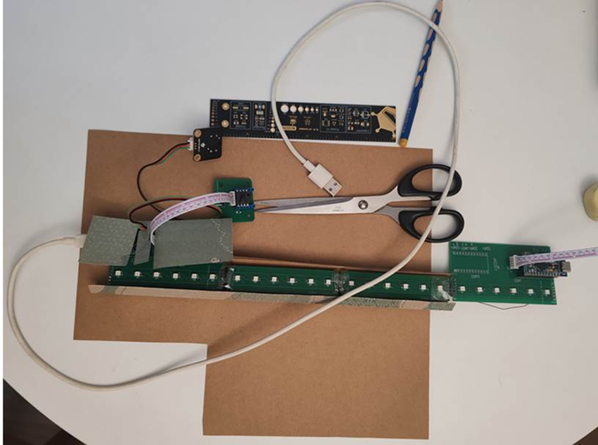
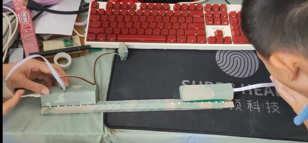
游戏的时候双方对着传感器吹气即可:
遇到的难点及解决方法
1. NSPGD1M006DT04传感器无法设定设备地址,因此 I2C 上只能放置一个。如果有需要,那么可以通过 GPIO 来进行模拟,或者通过添加元件来解决。最终选择的方案是使用2个Arduino 这样可以化简电路,方便代码编写;
2. 两个 Arduino 使用串口通讯,Arduino Leonardo 中 float 占用4字节。为了简单起见,采用直接将float 拆开然后加上识别头的方法来进行传输
工作的视频
本文提到的 PCB 和代码下载:
====================================================
本文是2025年参加电子森林活动的项目,获得优秀奖
在Buffer 中显示 Ascii
编写了一个代码,在一个 160*120 Buffer 中显示 Ascii。
这个代码可以看作实现了一个简单的字库。
VS2019 代码如下:
#include <stdio.h>
#include <string.h>
#include <stdint.h>
#include <windows.h>

// 显示缓冲区尺寸
#define BUFFER_WIDTH  160
#define BUFFER_HEIGHT 120

// 字符尺寸 (8x8像素)
#define CHAR_WIDTH  8
#define CHAR_HEIGHT 8

// 计算可显示的字符数量
#define CHARS_PER_ROW (BUFFER_WIDTH / CHAR_WIDTH)   // 20个字符
#define CHARS_PER_COL (BUFFER_HEIGHT / CHAR_HEIGHT) // 15行

// 显示缓冲区
uint8_t display_buffer[BUFFER_HEIGHT][BUFFER_WIDTH];

// 修正后的ASCII字符字体数据 (8x8像素,可见字符32-126)
const uint8_t ascii_font[95][8] = {
    // 空格 (32)
    {0x00, 0x00, 0x00, 0x00, 0x00, 0x00, 0x00, 0x00},
    // ! (33)
    {0x18, 0x18, 0x18, 0x18, 0x18, 0x00, 0x18, 0x00},
    // " (34)
    {0x6C, 0x6C, 0x6C, 0x00, 0x00, 0x00, 0x00, 0x00},
    // # (35)
    {0x6C, 0x6C, 0xFE, 0x6C, 0xFE, 0x6C, 0x6C, 0x00},
    // $ (36)
    {0x30, 0x7C, 0xC0, 0x78, 0x0C, 0xF8, 0x30, 0x00},
    // % (37)
    {0x00, 0xC6, 0xCC, 0x18, 0x30, 0x66, 0xC6, 0x00},
    // & (38)
    {0x38, 0x6C, 0x38, 0x76, 0xDC, 0xCC, 0x76, 0x00},
    // ' (39)
    {0x60, 0x60, 0xC0, 0x00, 0x00, 0x00, 0x00, 0x00},
    // ( (40)
    {0x18, 0x30, 0x60, 0x60, 0x60, 0x30, 0x18, 0x00},
    // ) (41)
    {0x60, 0x30, 0x18, 0x18, 0x18, 0x30, 0x60, 0x00},
    // * (42)
    {0x00, 0x66, 0x3C, 0xFF, 0x3C, 0x66, 0x00, 0x00},
    // + (43)
    {0x00, 0x30, 0x30, 0xFC, 0x30, 0x30, 0x00, 0x00},
    // , (44)
    {0x00, 0x00, 0x00, 0x00, 0x00, 0x30, 0x60, 0x00},
    // - (45)
    {0x00, 0x00, 0x00, 0xFC, 0x00, 0x00, 0x00, 0x00},
    // . (46)
    {0x00, 0x00, 0x00, 0x00, 0x00, 0x30, 0x30, 0x00},
    // / (47)
    {0x06, 0x0C, 0x18, 0x30, 0x60, 0xC0, 0x80, 0x00},
    // 0 (48)
    {0x7C, 0xC6, 0xCE, 0xDE, 0xF6, 0xE6, 0x7C, 0x00},
    // 1 (49)
    {0x30, 0x70, 0x30, 0x30, 0x30, 0x30, 0xFC, 0x00},
    // 2 (50)
    {0x78, 0xCC, 0x0C, 0x38, 0x60, 0xCC, 0xFC, 0x00},
    // 3 (51)
    {0x78, 0xCC, 0x0C, 0x38, 0x0C, 0xCC, 0x78, 0x00},
    // 4 (52)
    {0x1C, 0x3C, 0x6C, 0xCC, 0xFE, 0x0C, 0x1E, 0x00},
    // 5 (53)
    {0xFC, 0xC0, 0xF8, 0x0C, 0x0C, 0xCC, 0x78, 0x00},
    // 6 (54)
    {0x38, 0x60, 0xC0, 0xF8, 0xCC, 0xCC, 0x78, 0x00},
    // 7 (55)
    {0xFC, 0xCC, 0x0C, 0x18, 0x30, 0x30, 0x30, 0x00},
    // 8 (56)
    {0x78, 0xCC, 0xCC, 0x78, 0xCC, 0xCC, 0x78, 0x00},
    // 9 (57)
    {0x78, 0xCC, 0xCC, 0x7C, 0x0C, 0x18, 0x70, 0x00},
    // : (58)
    {0x00, 0x30, 0x30, 0x00, 0x00, 0x30, 0x30, 0x00},
    // ; (59)
    {0x00, 0x30, 0x30, 0x00, 0x00, 0x30, 0x60, 0x00},
    // < (60)
    {0x18, 0x30, 0x60, 0xC0, 0x60, 0x30, 0x18, 0x00},
    // = (61)
    {0x00, 0x00, 0xFC, 0x00, 0x00, 0xFC, 0x00, 0x00},
    // > (62)
    {0x60, 0x30, 0x18, 0x0C, 0x18, 0x30, 0x60, 0x00},
    // ? (63)
    {0x78, 0xCC, 0x0C, 0x18, 0x30, 0x00, 0x30, 0x00},
    // @ (64)
    {0x7C, 0xC6, 0xDE, 0xDE, 0xDE, 0xC0, 0x78, 0x00},
    // A (65)
    {0x30, 0x78, 0xCC, 0xCC, 0xFC, 0xCC, 0xCC, 0x00},
    // B (66)
    {0xFC, 0x66, 0x66, 0x7C, 0x66, 0x66, 0xFC, 0x00},
    // C (67)
    {0x3C, 0x66, 0xC0, 0xC0, 0xC0, 0x66, 0x3C, 0x00},
    // D (68)
    {0xF8, 0x6C, 0x66, 0x66, 0x66, 0x6C, 0xF8, 0x00},
    // E (69)
    {0xFE, 0x62, 0x68, 0x78, 0x68, 0x62, 0xFE, 0x00},
    // F (70)
    {0xFE, 0x62, 0x68, 0x78, 0x68, 0x60, 0xF0, 0x00},
    // G (71)
    {0x3C, 0x66, 0xC0, 0xC0, 0xCE, 0x66, 0x3E, 0x00},
    // H (72)
    {0xCC, 0xCC, 0xCC, 0xFC, 0xCC, 0xCC, 0xCC, 0x00},
    // I (73)
    {0x78, 0x30, 0x30, 0x30, 0x30, 0x30, 0x78, 0x00},
    // J (74)
    {0x1E, 0x0C, 0x0C, 0x0C, 0xCC, 0xCC, 0x78, 0x00},
    // K (75)
    {0xE6, 0x66, 0x6C, 0x78, 0x6C, 0x66, 0xE6, 0x00},
    // L (76)
    {0xF0, 0x60, 0x60, 0x60, 0x62, 0x66, 0xFE, 0x00},
    // M (77)
    {0xC6, 0xEE, 0xFE, 0xFE, 0xD6, 0xC6, 0xC6, 0x00},
    // N (78)
    {0xC6, 0xE6, 0xF6, 0xDE, 0xCE, 0xC6, 0xC6, 0x00},
    // O (79)
    {0x38, 0x6C, 0xC6, 0xC6, 0xC6, 0x6C, 0x38, 0x00},
    // P (80)
    {0xFC, 0x66, 0x66, 0x7C, 0x60, 0x60, 0xF0, 0x00},
    // Q (81)
    {0x78, 0xCC, 0xCC, 0xCC, 0xDC, 0x78, 0x1C, 0x00},
    // R (82)
    {0xFC, 0x66, 0x66, 0x7C, 0x6C, 0x66, 0xE6, 0x00},
    // S (83)
    {0x78, 0xCC, 0xE0, 0x70, 0x1C, 0xCC, 0x78, 0x00},
    // T (84)
    {0xFC, 0xB4, 0x30, 0x30, 0x30, 0x30, 0x78, 0x00},
    // U (85)
    {0xCC, 0xCC, 0xCC, 0xCC, 0xCC, 0xCC, 0xFC, 0x00},
    // V (86)
    {0xCC, 0xCC, 0xCC, 0xCC, 0xCC, 0x78, 0x30, 0x00},
    // W (87)
    {0xC6, 0xC6, 0xC6, 0xD6, 0xFE, 0xEE, 0xC6, 0x00},
    // X (88)
    {0xC6, 0xC6, 0x6C, 0x38, 0x38, 0x6C, 0xC6, 0x00},
    // Y (89)
    {0xCC, 0xCC, 0xCC, 0x78, 0x30, 0x30, 0x78, 0x00},
    // Z (90)
    {0xFE, 0xC6, 0x8C, 0x18, 0x32, 0x66, 0xFE, 0x00},
    // [ (91)
    {0x78, 0x60, 0x60, 0x60, 0x60, 0x60, 0x78, 0x00},
    // \ (92)
    {0xC0, 0x60, 0x30, 0x18, 0x0C, 0x06, 0x02, 0x00},
    // ] (93)
    {0x78, 0x18, 0x18, 0x18, 0x18, 0x18, 0x78, 0x00},
    // ^ (94)
    {0x10, 0x38, 0x6C, 0xC6, 0x00, 0x00, 0x00, 0x00},
    // _ (95)
    {0x00, 0x00, 0x00, 0x00, 0x00, 0x00, 0x00, 0xFF},
    // ` (96)
    {0x30, 0x30, 0x18, 0x00, 0x00, 0x00, 0x00, 0x00},
    // a (97)
    {0x00, 0x00, 0x78, 0x0C, 0x7C, 0xCC, 0x76, 0x00},
    // b (98)
    {0xE0, 0x60, 0x60, 0x7C, 0x66, 0x66, 0xDC, 0x00},
    // c (99)
    {0x00, 0x00, 0x78, 0xCC, 0xC0, 0xCC, 0x78, 0x00},
    // d (100)
    {0x1C, 0x0C, 0x0C, 0x7C, 0xCC, 0xCC, 0x76, 0x00},
    // e (101)
    {0x00, 0x00, 0x78, 0xCC, 0xFC, 0xC0, 0x78, 0x00},
    // f (102)
    {0x38, 0x6C, 0x60, 0xF0, 0x60, 0x60, 0xF0, 0x00},
    // g (103)
    {0x00, 0x00, 0x76, 0xCC, 0xCC, 0x7C, 0x0C, 0xF8},
    // h (104)
    {0xE0, 0x60, 0x6C, 0x76, 0x66, 0x66, 0xE6, 0x00},
    // i (105)
    {0x30, 0x00, 0x70, 0x30, 0x30, 0x30, 0x78, 0x00},
    // j (106)
    {0x0C, 0x00, 0x0C, 0x0C, 0x0C, 0xCC, 0xCC, 0x78},
    // k (107)
    {0xE0, 0x60, 0x66, 0x6C, 0x78, 0x6C, 0xE6, 0x00},
    // l (108)
    {0x70, 0x30, 0x30, 0x30, 0x30, 0x30, 0x78, 0x00},
    // m (109)
    {0x00, 0x00, 0xCC, 0xFE, 0xFE, 0xD6, 0xC6, 0x00},
    // n (110)
    {0x00, 0x00, 0xF8, 0xCC, 0xCC, 0xCC, 0xCC, 0x00},
    // o (111)
    {0x00, 0x00, 0x78, 0xCC, 0xCC, 0xCC, 0x78, 0x00},
    // p (112)
    {0x00, 0x00, 0xDC, 0x66, 0x66, 0x7C, 0x60, 0xF0},
    // q (113)
    {0x00, 0x00, 0x76, 0xCC, 0xCC, 0x7C, 0x0C, 0x1E},
    // r (114)
    {0x00, 0x00, 0xDC, 0x76, 0x66, 0x60, 0xF0, 0x00},
    // s (115)
    {0x00, 0x00, 0x7C, 0xC0, 0x78, 0x0C, 0xF8, 0x00},
    // t (116)
    {0x10, 0x30, 0x7C, 0x30, 0x30, 0x34, 0x18, 0x00},
    // u (117)
    {0x00, 0x00, 0xCC, 0xCC, 0xCC, 0xCC, 0x76, 0x00},
    // v (118)
    {0x00, 0x00, 0xCC, 0xCC, 0xCC, 0x78, 0x30, 0x00},
    // w (119)
    {0x00, 0x00, 0xC6, 0xD6, 0xFE, 0xFE, 0x6C, 0x00},
    // x (120)
    {0x00, 0x00, 0xC6, 0x6C, 0x38, 0x6C, 0xC6, 0x00},
    // y (121)
    {0x00, 0x00, 0xCC, 0xCC, 0xCC, 0x7C, 0x0C, 0xF8},
    // z (122)
    {0x00, 0x00, 0xFC, 0x98, 0x30, 0x64, 0xFC, 0x00},
    // { (123)
    {0x1C, 0x30, 0x30, 0xE0, 0x30, 0x30, 0x1C, 0x00},
    // | (124)
    {0x18, 0x18, 0x18, 0x00, 0x18, 0x18, 0x18, 0x00},
    // } (125)
    {0xE0, 0x30, 0x30, 0x1C, 0x30, 0x30, 0xE0, 0x00},
    // ~ (126)
    {0x76, 0xDC, 0x00, 0x00, 0x00, 0x00, 0x00, 0x00}
};


// 清空显示缓冲区
void clear_buffer() {
    memset(display_buffer, 0, sizeof(display_buffer));
}

// 在指定位置绘制单个字符
void draw_char(int x, int y, char c) {
    if (c < 32 || c > 126) return; // 只支持可见ASCII字符

    int char_index = c - 32;
    const uint8_t* font_data = ascii_font[char_index];

    for (int row = 0; row < CHAR_HEIGHT; row++) {
        if (y + row >= BUFFER_HEIGHT) break;

        uint8_t font_row = font_data[row];
        for (int col = 0; col < CHAR_WIDTH; col++) {
            if (x + col >= BUFFER_WIDTH) break;

            if (font_row & (0x80 >> col)) {
                display_buffer[y + row][x + col] = 1;
            }
        }
    }
}

// 在指定字符位置绘制字符(自动计算像素位置)
void draw_char_at_pos(int char_x, int char_y, char c) {
    if (char_x >= CHARS_PER_ROW || char_y >= CHARS_PER_COL) return;

    int pixel_x = char_x * CHAR_WIDTH;
    int pixel_y = char_y * CHAR_HEIGHT;
    draw_char(pixel_x, pixel_y, c);
}

// 绘制字符串
void draw_string(int char_x, int char_y, const char* str) {
    int x = char_x;
    int y = char_y;

    while (*str && y < CHARS_PER_COL) {
        if (*str == '\n') {
            x = char_x;
            y++;
        }
        else {
            if (x < CHARS_PER_ROW) {
                draw_char_at_pos(x, y, *str);
                x++;
            }
            else {
                // 自动换行
                x = char_x;
                y++;
                if (y < CHARS_PER_COL) {
                    draw_char_at_pos(x, y, *str);
                    x++;
                }
            }
        }
        str++;
    }
}

// 打印缓冲区内容(用于调试)
void print_buffer() {
    for (int y = 0; y < BUFFER_HEIGHT; y++) {
        for (int x = 0; x < BUFFER_WIDTH; x++) {
            printf("%c", display_buffer[y][x] ? '#' : '.');
        }
        printf("\n");
    }
}

void SetConsoleSize(int width, int height) {
    HANDLE hConsole = GetStdHandle(STD_OUTPUT_HANDLE);

    // 设置缓冲区大小
    COORD bufferSize = { (SHORT)width, (SHORT)height };
    SetConsoleScreenBufferSize(hConsole, bufferSize);

    // 设置窗口大小
    SMALL_RECT windowSize = { 0, 0, (SHORT)(width - 1), (SHORT)(height - 1) };
    SetConsoleWindowInfo(hConsole, TRUE, &windowSize);
}

// 示例使用
int main() {
    // 设置控制台为160列x120行
    SetConsoleSize(160, 120);

    // 清空缓冲区
    clear_buffer();

    // 绘制一些文本
    draw_string(0, 1, "ASCII Display Test");
    draw_string(0, 2, "0123456789");
    draw_string(0, 3, "ABCDEFGHIJKLMNOPQRST");
    draw_string(0, 4, "abcdefghijklmnopqrst");
    draw_string(0, 5, "!@#$%^&*()_+-=[]{}|;");
    draw_string(0, 6, "':\",./<>?`~");

    print_buffer();

    printf("Display buffer size: %dx%d pixels\n", BUFFER_WIDTH, BUFFER_HEIGHT);
    printf("Character grid: %dx%d characters\n", CHARS_PER_ROW, CHARS_PER_COL);
    printf("Output saved to display_output.pbm\n");

    return 0;
}
运行结果:

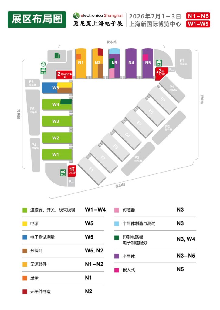
2026年上海慕尼黑电子展
现在的上海正处于梅雨季,连续的阴雨让气温完全没有夏季的感觉。今年的慕尼黑电子展是7月1日到3日,和往年一样,我前往参观。
本次展览在上海新国际博览中心进行,在上海估计地铁是最方面的到达方式,场馆就在龙阳路地铁站旁边。

场馆外的大型海报
刚到时,雨还没有停,门口有着各式各样的大型海报。

RISC-V 的广告牌,相比 ARM ,RISC-V 有着巨大的成本优势

DigiKey 的巨大广告牌,他们是颇有实力的零件分销商
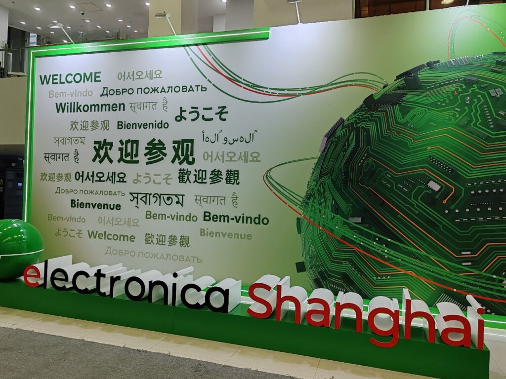
进场之后的海报,很多人在此驻足拍照留念
首先走马观花了Murata(株式会社村田制作所)展位:

Murata展位
这是他家推出的超声波传感器,我不清楚这种和激光测距有什么优势:
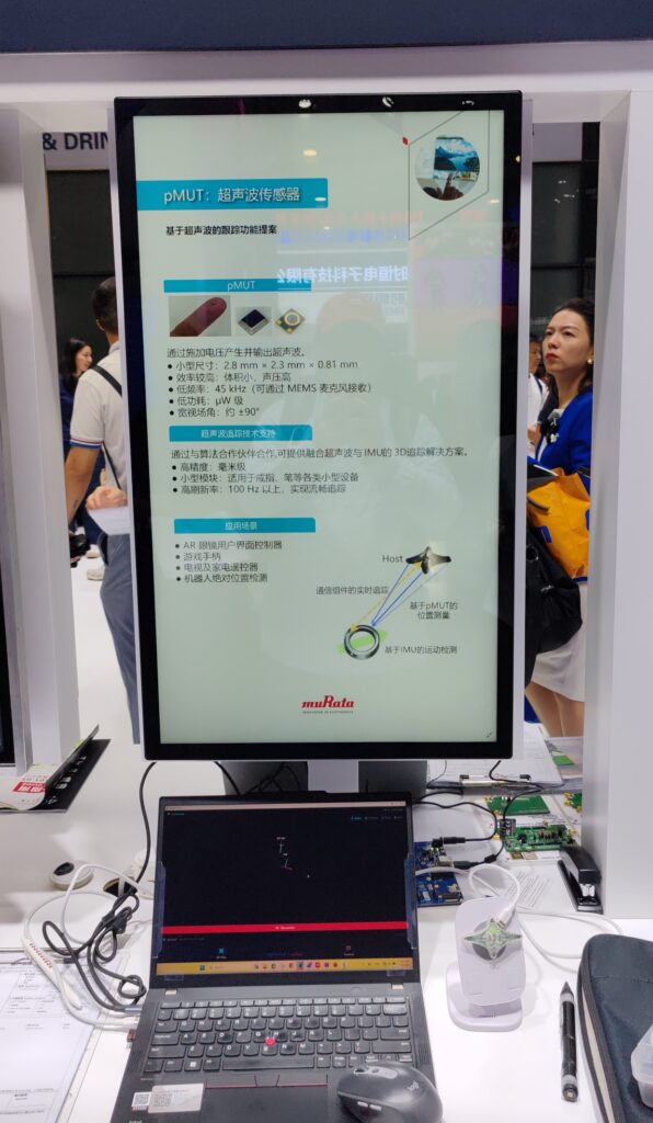
可以通过超声波实现定位跟踪
感觉这家企业正在努力转型,从常见的电容电感产品转向更精密的专用传感器,作为老牌元器件厂商,这家企业的营理念强调“磨砺精湛技术、供应独特产品”。
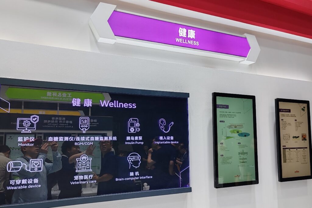
有可以用于测量血压的气泵以及胰岛素泵
我业余时间一直在玩USB相关的内容,特别关注了一下 WCH (沁恒微电子)。

这家公司的 MCU 主推 RISC-V 产品线,有着覆盖从低端到高端的MCU (特别是USB 3.0 MCU ,几乎是普通人能拿到支持的唯一选择)
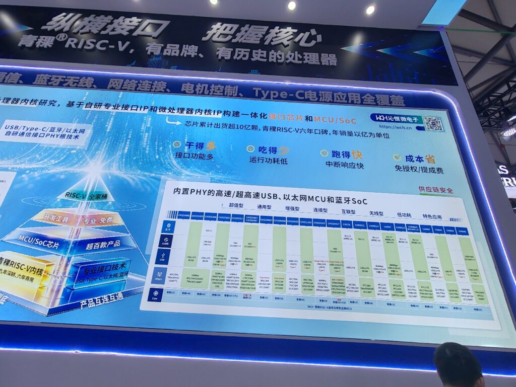
可以看到目前主要有USB/以太网/蓝牙三大产品线
除了USB目前WCH还在深耕蓝牙和无线技术:
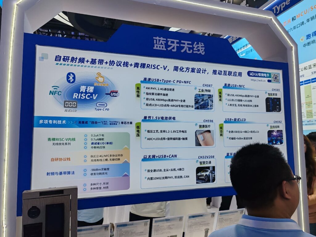
蓝牙无线
现场看到的比较特别的产品有CH390芯片,体积极小的芯片能够轻松的给你产品插上有线网络的翅膀:
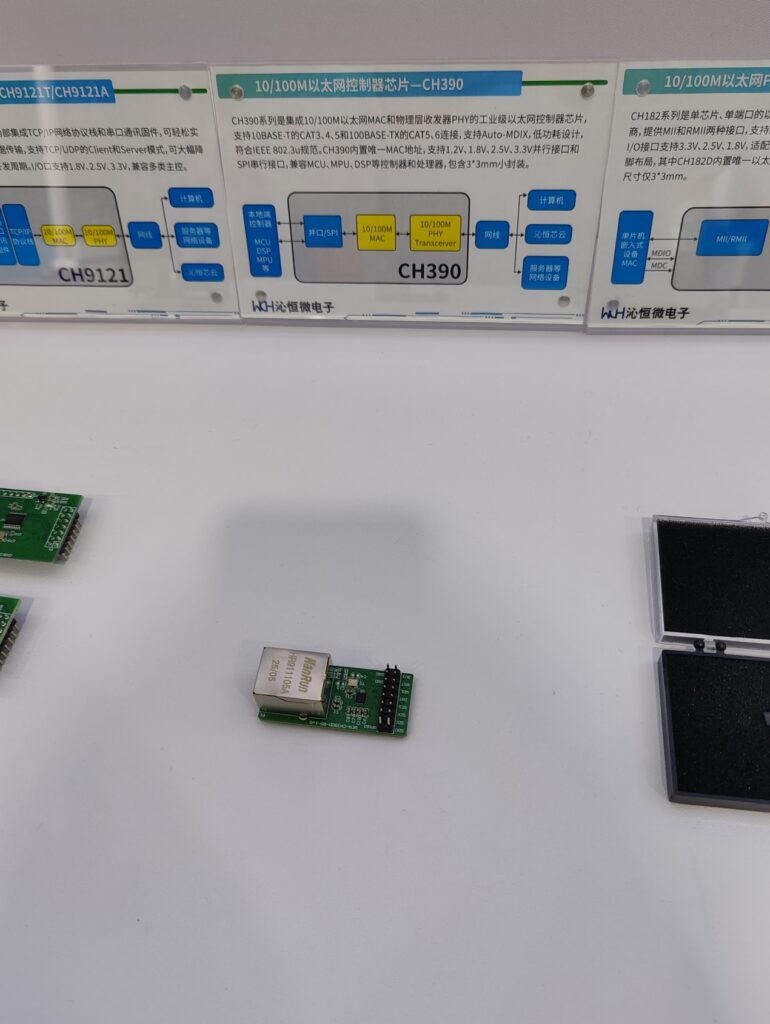
CH390 测试板
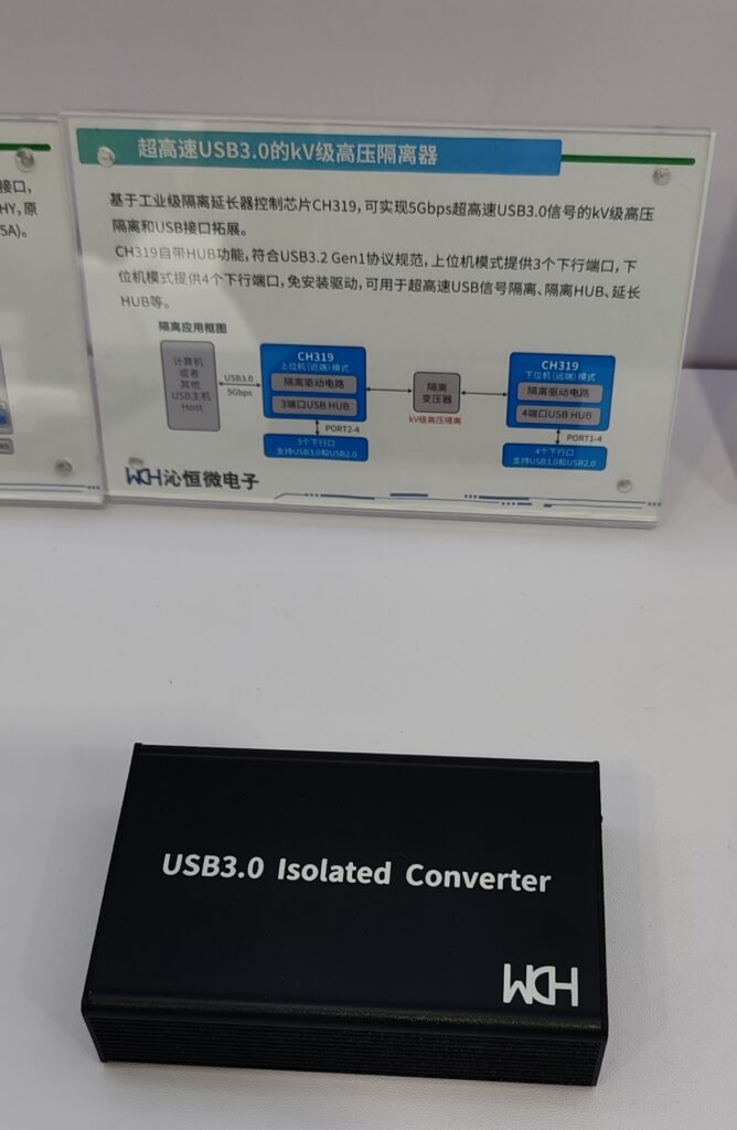
此外,还有USB 3.0隔离器。在我们的笔记本电脑上,USB 通常是直通 SoC 的(我只在一款 ThinkPad 的 产品上见过USB2.0的隔离设计)。如果在现场使用USB 进行调试,会有电流倒灌损坏 SoC 的风险。这种隔离器能够帮助你安心的使用USB 进行调试。作为BIOS工程师,我真心希望能有公司在研发设计笔记本时以寿命为目标。
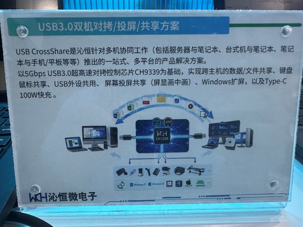
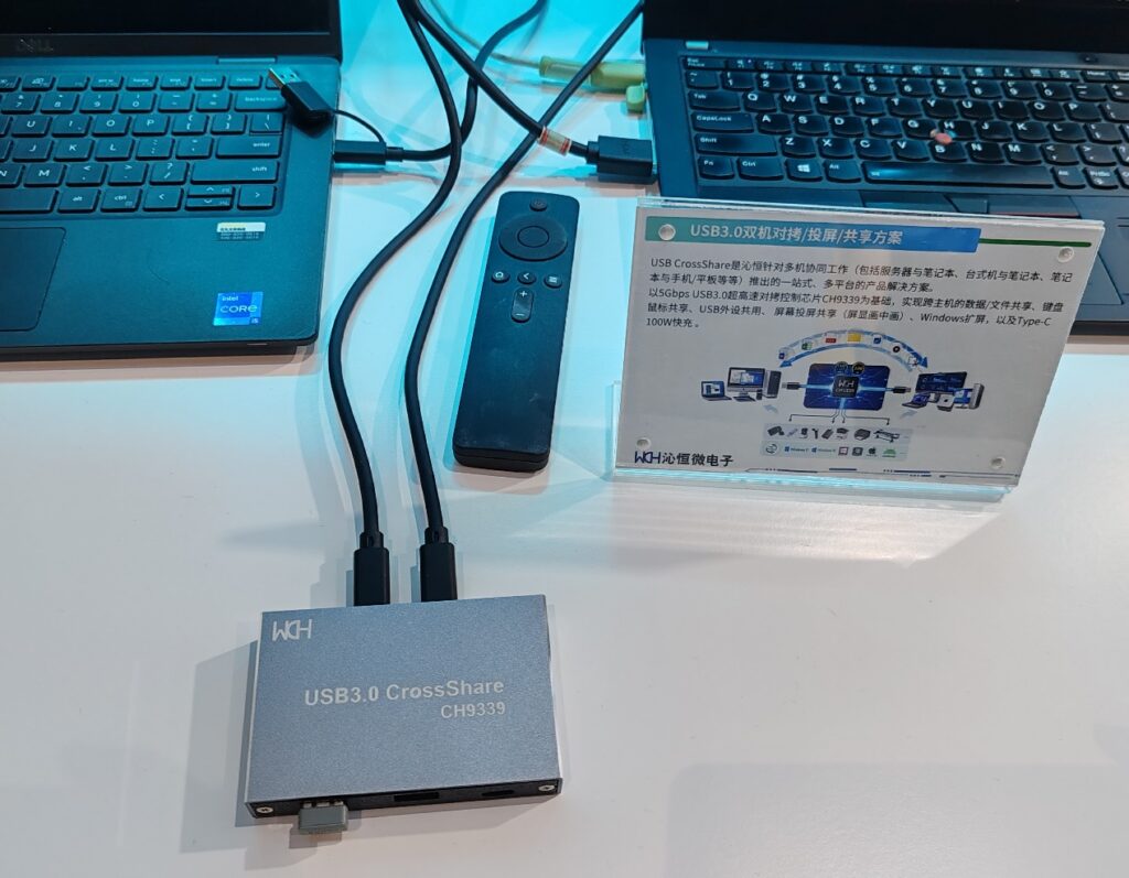
此外,这次还见到了CH9338(USB2.0)的下一代 USB3.0 双机互联方案 CH9339,USB3.0 的速度更快,同时还提供了双机同屏的功能。
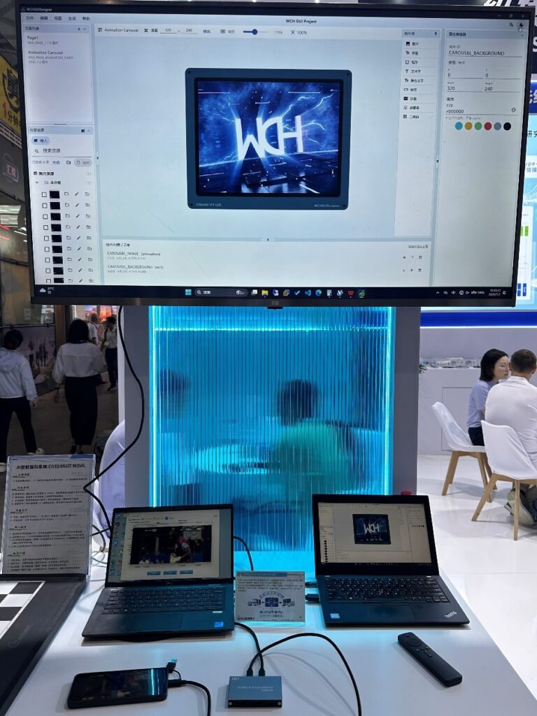
这里有更详细的产品介绍:
接下来是作为 DIY 爱好者,我经常使用的品牌。
首先是嘉立创集团,在这次展会上他们有2个展位

嘉立创集团的展位
现在可以在嘉立创 FA 进行铝合金外壳定制
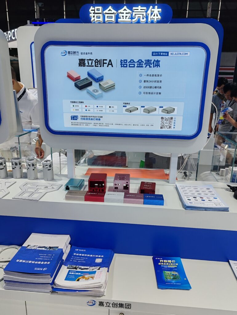
可以直接进行产品外壳的定制
作为 DIY 爱好者,我一直使用立创EDA绘制电路,我同EDA负责人进行了友好的交流。
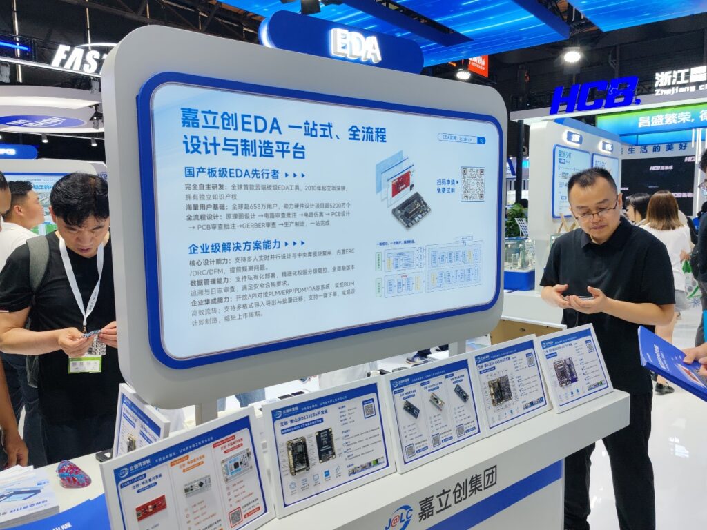
嘉立创 EDA 展台
嘉立创PCB一直在坚持每月2片免费PCB , 帮助无数电子爱好者成长:
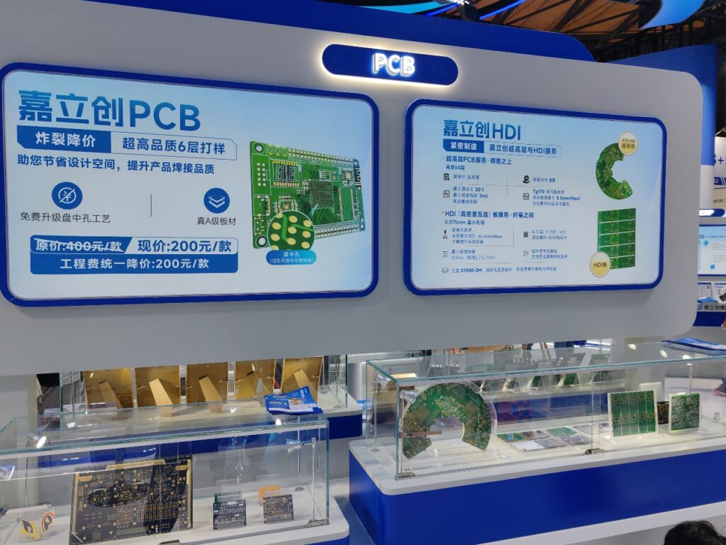
立创 EDA 设计出来的电路,可以直接在立创商城下单,这个避免了封装和元件不匹配的问题,同时因为立创硬件开源平台的存在,也能最大限度参考他人设计。用阿里巴巴的话术就是“以用户心智渗透为核心抓手,打通上下游链路,拉通各端口的需求对齐,把全流程的颗粒度拉平,完成从流量触达到价值闭环的全链路赋能,沉淀出可复用的行业方法论,最终实现生态内的反哺与双向共赢。”
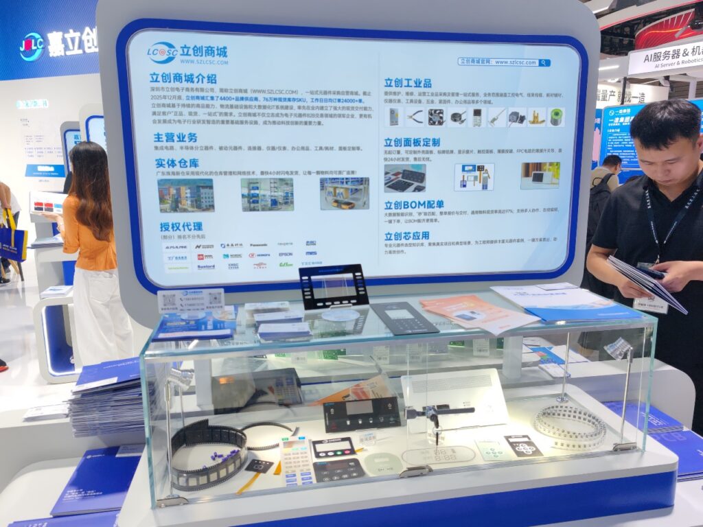
立创商城展位
微碧半导体,他们会在文章中分享一些 MOSFET 的设计,比如,电池防止反装。我在设计上用过他们的芯片。


微盟电子是一家南京的企业,有一些 LDO、DC-DC 的产品,如果你电压转换的需求,除了 TI 的手册还可以翻翻他们的产品手册。

厚声集团,我用过他们的很多电阻:

圣邦微电子,在大部分笔记本电脑上都会使用他们的供电芯片方案

优利德,是老牌的国产测量仪器厂商,很多人第一次接触这个品牌都是万用表,这次展出的都是示波器产品。
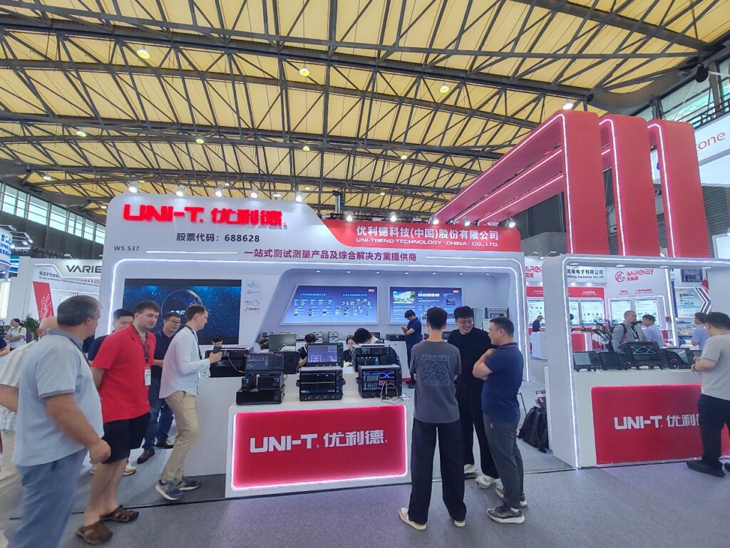
它的对面是同样做示波器的鼎阳品牌
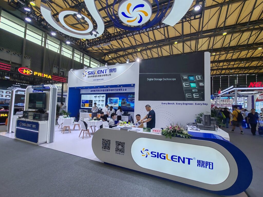
鼎阳展位
还有 KeySight,当然,这种品牌对于 DIY 用户已经过于高端了

这次还看到了一家国产 MRAM 存储芯片制造商,这是我第一次听说 MRAM,查询资料得知MRAM(Magnetoresistive Random Access Memory) 是一种非易失性的磁性随机存储器,它利用磁电阻效应来存储数据。与传统的半导体随机存取存储器(RAM)不同,MRAM使用磁性隧道结(MTJ)作为存储单元,通过改变磁化方向来记录二进制数据。就是说它不需要电力维持存储,更无惧随机掉电。据说存储速度也很高。只是暂时我还想不出有什么必须的应用场景。

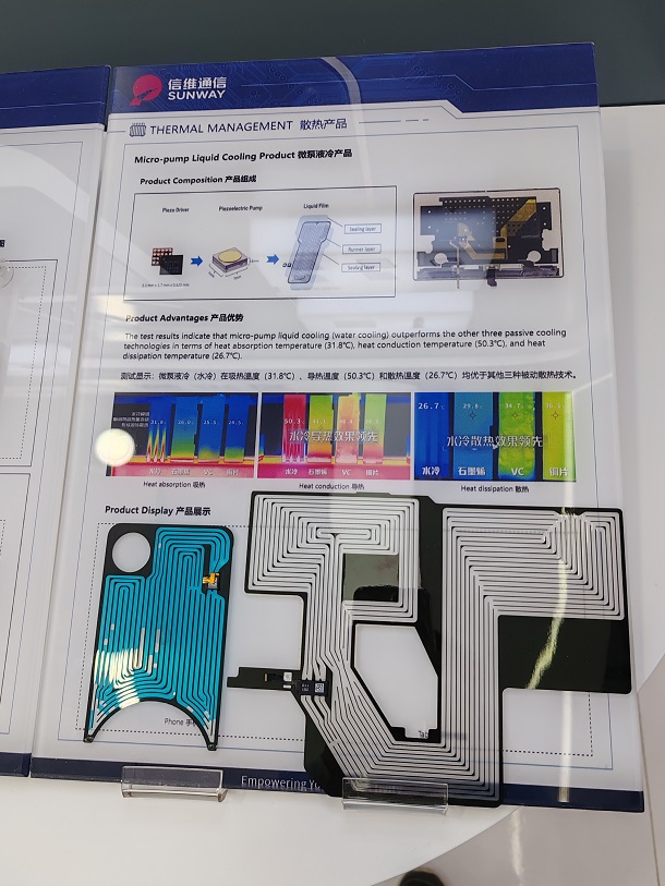
信维通信的站台上看到了微泵液冷的散热方案,不过可惜现场没有相关资料

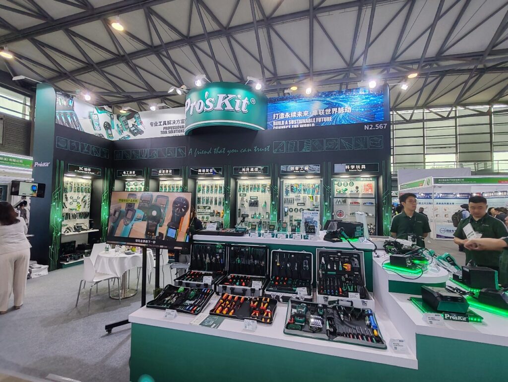
最后讲个好玩的,没想到 Pro’s Kit(宝工)有一个很大的展位。在我仔细端详的时候,小哥热情的和我聊天。我表示作为DIY爱好者,手上有很多你们的螺丝刀之类的产品。在小哥露出满意的神情后,他问了一个让我和他都后悔的问题:你觉得我们的产品还有什么需要改进的地方吗?我脱口而出:太容易生锈。说出来之后我也觉得有些尴尬。急忙补充道:在公司用没问题,但是家用会生锈。小哥想了想终于又问出来一句:是手柄生锈吗?我回答:螺丝刀的头生锈……之后我也急忙离去避免持续的尴尬。
工业界相比学界更加务实,在整个展览中并没有太多的“AI”概念,相比往年,稍微多了一些机器人伺服电机关节的内容。
元件国产化已经是非常明显的趋势,伴随着这种趋势国产元件也在努力实践中证明自己。选用国产元件可以保证及时的供应和支持。
这次展览展馆分布如下,有兴趣的朋友还可以前往观看。
Step to UEFI (310)EDK2 中使用 LIB加入编译
LIB (Static Library – 静态库)和 DLL (Dynamic Link Library – 动态链接库) 都是库文件,他们存在一些差别。比如,LIB 是编译期加入到文件中,成为 EFI 或者 EXE 的一部分。而DLL则是在运行期独立存放在内存中进行调用的。
这次的实验是:在 VS2019 中使用C生成一个 LIB, 然后在 EDK2 环境下调用这个LIB。
首先编写 LIB ,源代码非常简单,LibFile.c 源代码如下:
///
/// 8-byte unsigned value
///
typedef unsigned long long int UINT64;

///
/// Unsigned value of native width.  (4 bytes on supported 32-bit processor instructions,
/// 8 bytes on supported 64-bit processor instructions)
///
typedef UINT64  UINTN;

#define EFIAPI __cdecl  // Force C calling convention for Microsoft C compiler

#define IN

UINTN
EFIAPI
MyLibAdd(
    IN UINTN A,
    IN UINTN B
)
{
    return A + B;
}
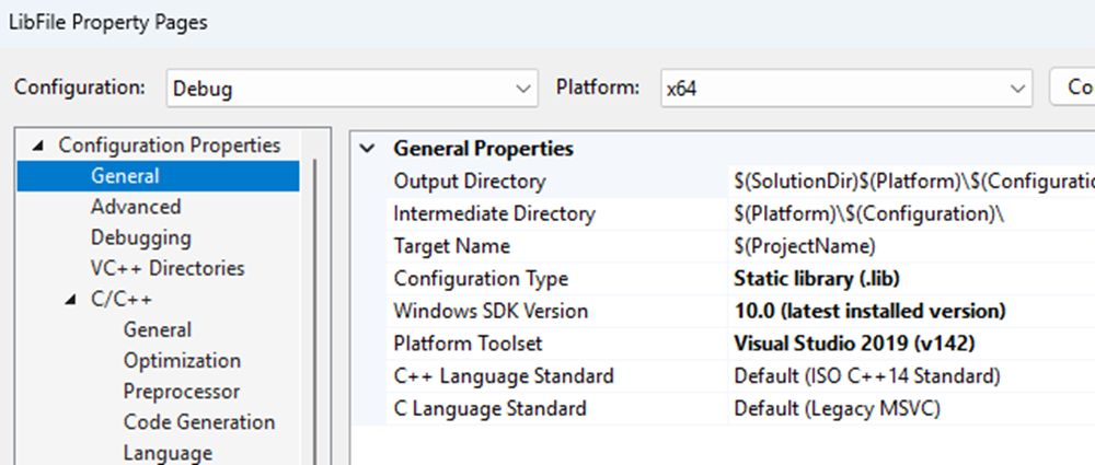
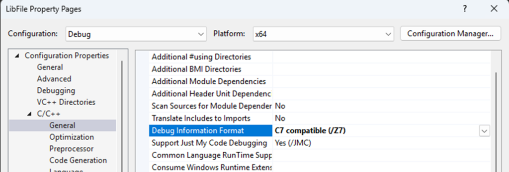
项目属性中设置编译目标为 Lib:
Debug 信息格式设置为 /Z7:
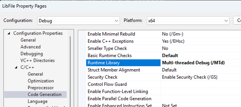
Runtime Library 设置为 /MTd
编译之后就得到了 LibFile.lib 文件。
接下来在 EDK2 中编写代码。
代码非常简单,关键点在于 extern 告诉链接器将要从外部调用 MyLibAdd() 函数。
#include  <Uefi.h>
#include  <Library/UefiLib.h>
#include  <Library/ShellCEntryLib.h>

extern UINTN EFIAPI MyLibAdd(IN UINTN A,IN UINTN B);

INTN
EFIAPI
ShellAppMain (
  IN UINTN Argc,
  IN CHAR16 **Argv
  )
{
  Print(L"LibTest Result: %d \n",MyLibAdd(1,2));

  return(0);
}
接下来编写 INF 文件,关键点在于 MSFT:*_*_*_DLINK_FLAGS 告诉 Lib 所在的目录位置。
[Defines]
  INF_VERSION                    = 0x00010006
  BASE_NAME                      = libtest
  FILE_GUID                      = a912f198-7f0e-2026-0429-b757b806ec83
  MODULE_TYPE                    = UEFI_APPLICATION
  VERSION_STRING                 = 0.1
  ENTRY_POINT                    = ShellCEntryLib

#
#  VALID_ARCHITECTURES           = IA32 X64
#

[Sources]
  LibTest.c

[Binaries]
  LIB|LibFile.lib

[Packages]
  MdePkg/MdePkg.dec
  ShellPkg/ShellPkg.dec

[LibraryClasses]
  UefiLib
  ShellCEntryLib

[BuildOptions]
  MSFT:*_*_*_DLINK_FLAGS = /LIBPATH:$(WORKSPACE)/AppPkg/Applications/LibTest LibFile.lib
特别注意:生成的 Lib 可以有 IA32 也可以有 X64, 同时还有 Release 和Debug 版本的区别,不可以混用。相对的,如果你要提供 LIB 给他人使用,那么很可能需要同时提供 Release 和 Debug 两个版本。本次实验测试的是 X64 Lib, Debug 版本。对应的编译命令是(Default 是 Debug 版本):
build -a X64 -p AppPkg\AppPkg.dsc -t VS2019
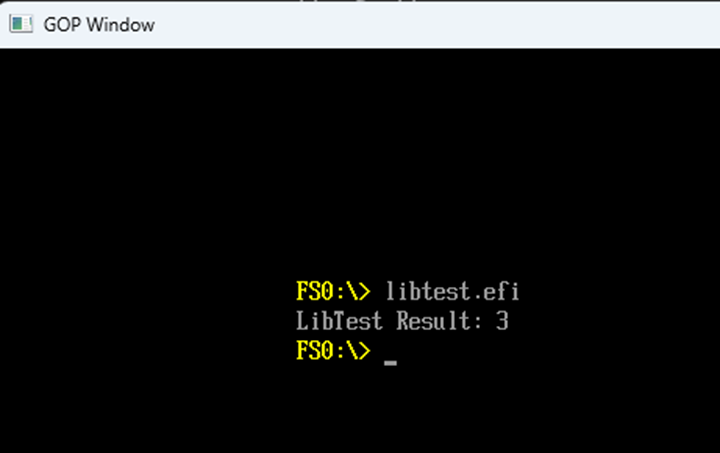
编译后的文件在模拟器中测试:
本次实验的VC 工程文件在这里下载:
本次实验的 EDK2 代码在这里下载: