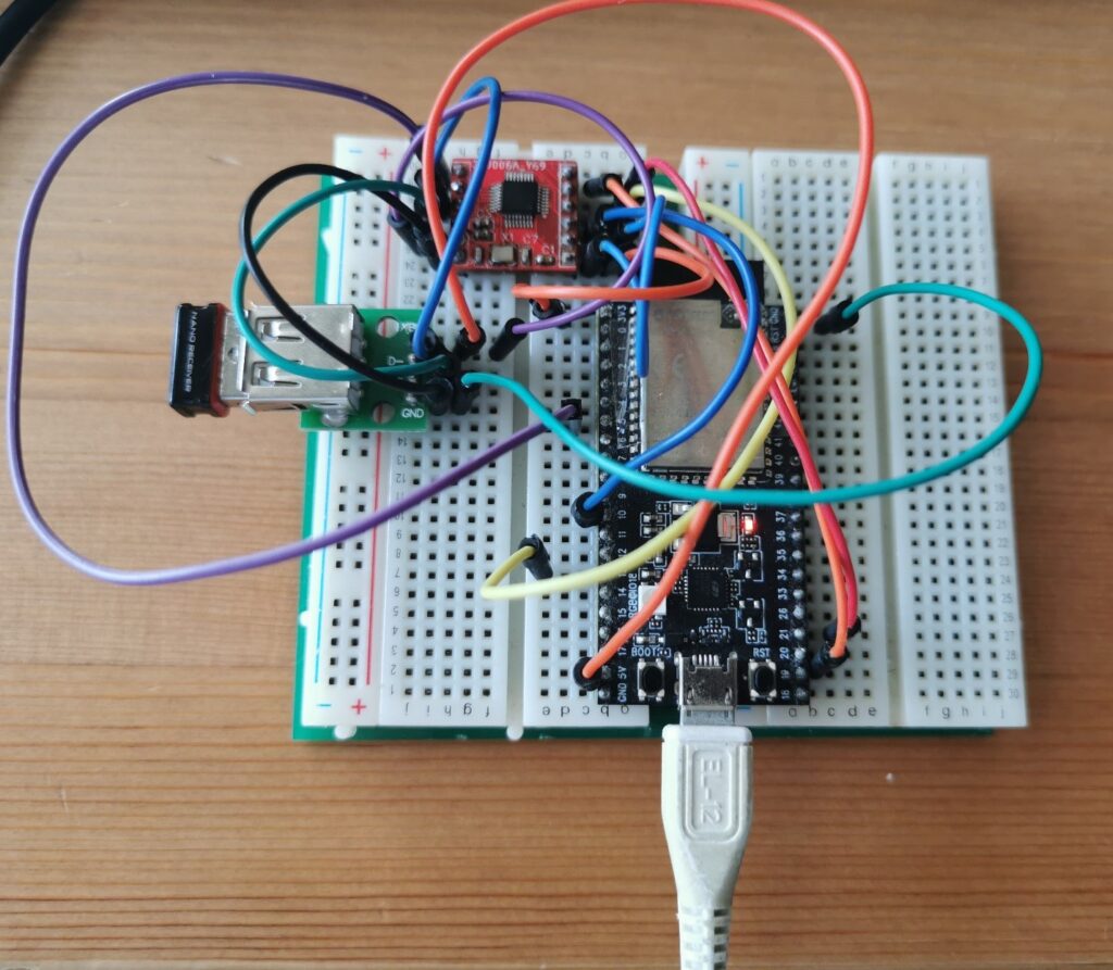
这次实验在 ESP32 S2 Saola 开发板上使用前面设计的Micro USB Host【参考1】。
首先遇到的问题是:ESP32 S2 的 SPI 在 Arduino 环境下工作不正常(对于这个问题的分析请参阅【参考2】)。为此,我们需要直接修改 位于 C:\Users\用户名\AppData\Local\Arduino15\packages\esp32\hardware\esp32\2.0.1\libraries\SPI\src\SPI.cpp 文件中的如下内容:
1 2 3 4 5 6 7 8 9 10 11 | #if CONFIG_IDF_TARGET_ESP32//LabZDebug_Start#if CONFIG_IDF_TARGET_ESP32S2 SPIClass SPI(HSPI);#else SPIClass SPI(VSPI);#endif//LabZDebug_End#elseSPIClass SPI(FSPI);#endif |
接下来修改 USB Host Shield 库文件:
- USB_Host_Shield_Library_2.0\usbhost.h 这个文件有下面3个地方需要修改:
- 1 这里给出用到的 SCK/MISO/MOSI/SS Pin的编号
1 2 3 4 5 6 7 | #elif defined(ESP32)//LABZDebug typedef SPi< P18, P23, P19, P5 > spi;//LABZDebug_Start //SCK MISO MOSI SStypedef SPi< P10, P21, P19, P13 > spi;//LABZDebug_End#elif defined(ARDUINO_NRF52840_FEATHER) |
1.2 给出SPI需要引脚编号才能正确的进行SPI初始化:
1 2 3 4 5 6 7 8 9 10 | #elif defined(SPI_HAS_TRANSACTION) static void init() { //LABZDebug USB_SPI.begin(); // The SPI library with transaction will take care of setting up the pins - settings is set in beginTransaction() //LABZDebug_Start USB_SPI.begin(10,21,19,13); // The SPI library with transaction will take care of setting up the pins - settings is set in beginTransaction() //LABZDebug_End SPI_SS::SetDirWrite(); SPI_SS::Set(); }#elif defined(STM32F4) |
1.3 降低速度(Max3421e 最高支持26Mhz, 但是因为 ESP32 无法分频出26M,所以实际上SPI 会以是20M速度工作。但是因为这次实验都是排线,所以频率高了之后会出现通讯错误的问题,为此需要进行降频)到4Mhz。
将文件中
1 2 3 4 | //LABZDebug USB_SPI.beginTransaction(SPISettings(26000000, MSBFIRST, SPI_MODE0)); // The MAX3421E can handle up to 26MHz, use MSB First and SPI mode 0//LABZDebug_StartUSB_SPI.beginTransaction(SPISettings(4000000, MSBFIRST, SPI_MODE0));//LABZDebug_End |
2.USB_Host_Shield_Library_2.0\UsbCore.h 这里给出用到的SS 和 INT Pin编号
1 2 3 4 5 6 7 8 | #elif defined(ESP32)//LABZDebug typedef MAX3421e<P5, P17> MAX3421E; // ESP32 boards//LABZDebug_Start // SS INTtypedef MAX3421e<P13, P5> MAX3421E; // ESP32 boards//LABZDebug_End#elif (defined(__AVR_ATmega644P__) || defined(__AVR_ATmega1284P__))typedef MAX3421e<Pb4, Pb3> MAX3421E; // Sanguino |
3.USB_Host_Shield_Library_2.0\avrpins.h 这里主要是声明前面用到的PXX 的定义否则编译会出错
1 2 3 4 5 6 7 | MAKE_PIN(P3, 3); // RX0//LABZDebug_StartMAKE_PIN(P4, 4); // INTMAKE_PIN(P13, 13); // CLKMAKE_PIN(P26, 26); // SS//LABZDebug_EndMAKE_PIN(P21, 21); // SDA |
之后使用 USBHIDBootMouse.ino 进行测试:
1 2 3 4 5 6 7 8 9 10 11 12 13 14 15 16 17 18 19 20 21 22 23 24 25 26 27 28 29 30 31 32 33 34 35 36 37 38 39 40 41 42 43 44 45 46 47 48 49 50 51 52 53 54 55 56 57 58 59 60 61 62 63 64 65 66 67 68 69 70 71 72 73 74 75 76 77 78 | #include <hidboot.h>#include <usbhub.h>// Satisfy the IDE, which needs to see the include statment in the ino too.#ifdef dobogusinclude#include <spi4teensy3.h>#endif#include <SPI.h>class MouseRptParser : public MouseReportParser{protected: void OnMouseMove (MOUSEINFO *mi); void OnLeftButtonUp (MOUSEINFO *mi); void OnLeftButtonDown (MOUSEINFO *mi); void OnRightButtonUp (MOUSEINFO *mi); void OnRightButtonDown (MOUSEINFO *mi); void OnMiddleButtonUp (MOUSEINFO *mi); void OnMiddleButtonDown (MOUSEINFO *mi);};void MouseRptParser::OnMouseMove(MOUSEINFO *mi){ Serial.print("dx="); Serial.print(mi->dX, DEC); Serial.print(" dy="); Serial.println(mi->dY, DEC);};void MouseRptParser::OnLeftButtonUp (MOUSEINFO *mi){ Serial.println("L Butt Up");};void MouseRptParser::OnLeftButtonDown (MOUSEINFO *mi){ Serial.println("L Butt Dn");};void MouseRptParser::OnRightButtonUp (MOUSEINFO *mi){ Serial.println("R Butt Up");};void MouseRptParser::OnRightButtonDown (MOUSEINFO *mi){ Serial.println("R Butt Dn");};void MouseRptParser::OnMiddleButtonUp (MOUSEINFO *mi){ Serial.println("M Butt Up");};void MouseRptParser::OnMiddleButtonDown (MOUSEINFO *mi){ Serial.println("M Butt Dn");};USB Usb;USBHub Hub(&Usb);HIDBoot<USB_HID_PROTOCOL_MOUSE> HidMouse(&Usb);MouseRptParser Prs;void setup(){ Serial.begin( 115200 );#if !defined(__MIPSEL__) while (!Serial); // Wait for serial port to connect - used on Leonardo, Teensy and other boards with built-in USB CDC serial connection#endif Serial.println("Start"); if (Usb.Init() == -1) Serial.println("OSC did not start."); delay( 200 ); HidMouse.SetReportParser(0, &Prs);}void loop(){ Usb.Task();} |
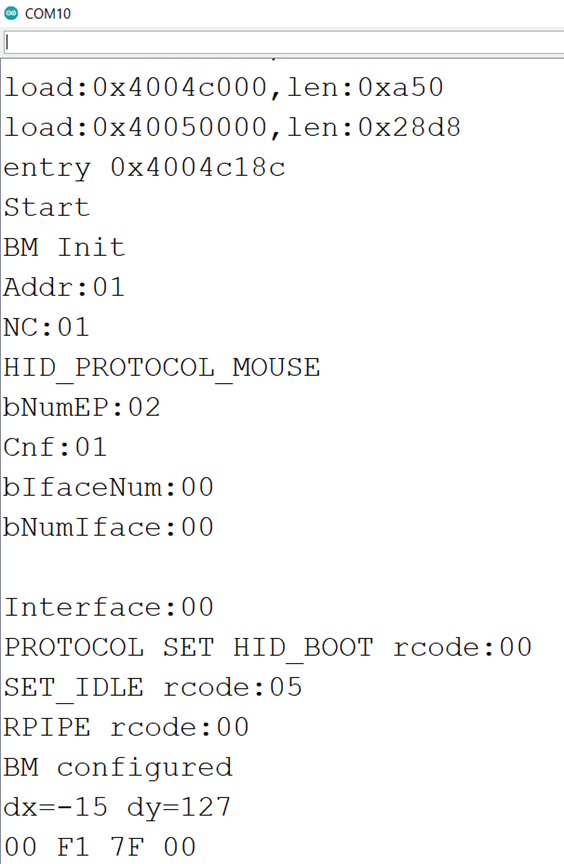
运行结果如下:
关于 USB Host Shield 调试建议如下:
- 首先跑 board_qc.ino 确定SPI 连接是否正确。如果一直有问题,那么是 SPI 不通,需要研究MOSI信号是否正常发送;如果 MOSI/SCLK 都正常但是没有 MOISO 回复,那么请检查 RESET 是否为高;
- 接下来跑USBHIDBootMouse.ino 代码测试,如果有问题,应该是 INT Pin 设置的错误;
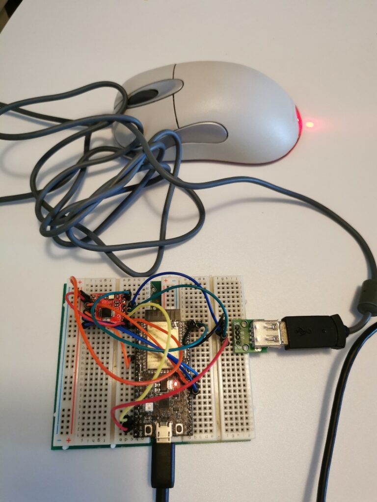
- 如果有线鼠标无法使用,那么可以实验无线鼠标,因为前者要求的功耗比较高,可能你从开发板中拉出来的5V供电不足。
参考:
- https://mc.dfrobot.com.cn/thread-312057-1-1.html 做一个Micro USB Host
- https://www.arduino.cn/thread-106240-1-1.html ESP32 S2 的 SPI
2022年5月28日 更新
偶然发现了 ESP32 S2 默认的 SPI 引脚【https://www.arduino.cn/thread-106240-1-1.html】,于是尝试不修改库的情况下直接使用。
硬件连接:
名称 | ESP32 S2 | ESP32 S2 | 名称 | |
| INT | IO17 | IO35 | MOSI | |
| GND | GND | IO37 | MISO | |
| MD- | USB 母头 D- | IO5 | SS | |
| MD+ | USB 母头 D+ | IO36 | SCLK | |
| VBCOMP | N/A | 3.3V | RESET | |
| GND | GND | 3.3V | 3.3V |
运行例子是 USB_Host_Shield_Library_2.0\examples\HID\USBHIDBootMouse
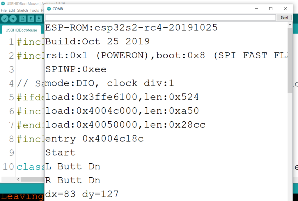
未经修改的 USB Host Shield 库如下: