How to use EADK

If you want to use C library in your program such as: printf, scanf……. You should use EADK library in EDK2.

1.Decompress EADK_A2_Release. There are 3 directories. Put them to your EDK2 source directory. In fact you should make sure your EDK2 can build and run NT32 well.
Capture

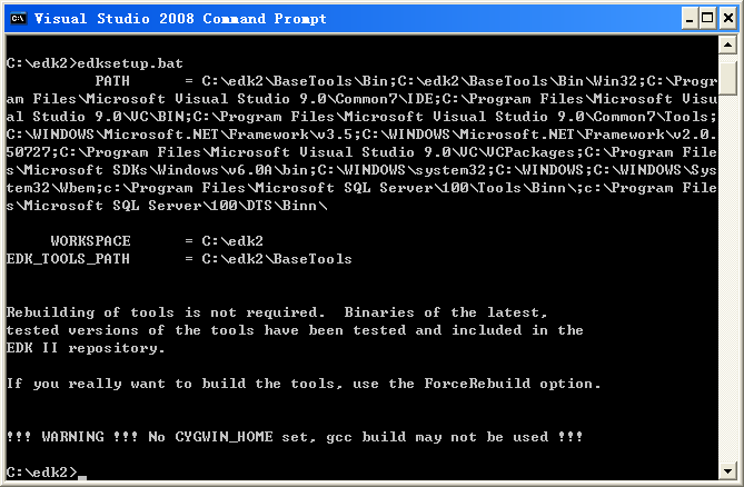
2.Run edksetup.bat in your EDK directory.

edksetup

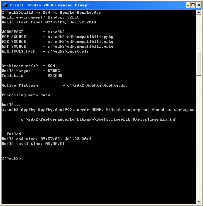
3.You can build EADK_A2_Release by using

build -a IA32 -p AppPkg\AppPkg.dsc

3.You well get the first error message.(AppPkg.dsc error 000E)

error1

4.You should modify AppPkg.dsc as below as we just want to test program under NT32:

[LibraryClasses.IA32]
# TimerLib|PerformancePkg/Library/DxeTscTimerLib/DxeTscTimerLib.inf
## Comment out the above line and un-comment the line below for running under Nt32 emulation.
TimerLib|MdePkg/Library/BaseTimerLibNullTemplate/BaseTimerLibNullTemplate.inf

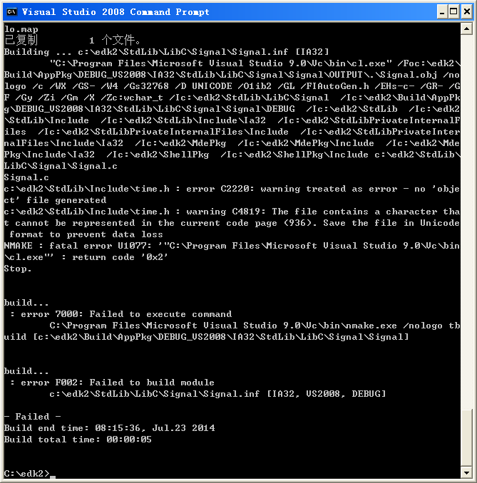
5.Build again and your will get the second error message (time.h Error C2220)

error2

6.The solution is simple. Use the Notepad to open the time.h and save again.

7.At last all the demos can be build. You can get main.efi hello.efi and Enquire.efi. They can be run in NT32 emulation environment.

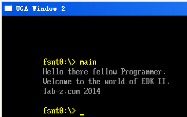
They will be placed at “\Build\AppPkg\DEBUG_VS2008\IA32” after compiling. And you can copy them to “\Build\NT32\DEBUG_VS2008\IA32”. After that they can be seen under fsnt0:

result

8.You can use printf in your program now. Ex.

int
EFIAPI
main (
IN int Argc,
IN char **Argv
)
{

puts(“Hello there fellow Programmer.”);
puts(“Welcome to the world of EDK II.”);

printf(“lab-z.com %x\n”,8212);

return 0;
}

result2

<2016> I find it seems to be hard to download an EADK package from internet, and I put one here EadkPkg_A2
reference:
1.http://www.lab-z.com/step-to-uefi-shell-6-shell-%E4%B8%AD%E4%BD%BF%E7%94%A8-float/

2.http://biosren.com/viewthread.php?tid=5651&fromuid=6339]http://biosren.com/viewthread.php?tid=5651&fromuid=6339 .UEFI 实战(1) 配置开发环境

D12 芯片的 0xFD Command在哪?

有人提了这么一个问题:

USB芯片PDIUSBD12读CHIP ID命令在手册中怎么找不到?

刚开始我以为只是没有拿到完整版的手册,后来找了一份比较新的结果里面也没有

PDIUSBD12D-0.9

遇到这样的情况,通常是要去找找 AP Note,找了一下还真找到了

What is the command to read the chip ID of the PDIUSBD12 and what is the chip ID?
The command to read the chip ID of the PDIUSBD12 is FDh and the expected value is 1012h.

PDIUSBD12_FAQ

最后一个没想明白的是,为毛我打开PDF中的网站 http://www.stnwireless.com/ 是下面的内容?莫非这个公司倒闭了,域名也卖掉了?

nxp

测试黄曲霉素

黄曲霉素是目前人类非常确定的致癌物,它被发现的原因是,1960年,英国发现有10万只火鸡死于一种以前没见过的病,被称为“火鸡X病”,再后来鸭子也被波及。经过研究最大的嫌疑是饲料。这些可怜的火鸡和鸭子吃的是花生饼。花生饼是花生榨油之后剩下的残渣,富含蛋白质,是很好的禽畜饲料。科学家们很快从花生饼中找到了罪魁祸首,一种真菌产生的毒素。它被命名为“aflatoxin ”。自那以后,黄曲霉毒素就获得了科学家们的特别关照,对它的研究可能是所有的真菌毒素中最深入最广泛的。[参考1]

因此,很简单的结论:一定要避免使用发霉的花生。另外一个问题则是:如果花生产生了黄曲霉素,那么用这样的花生压榨出来的花生油是否也会受到污染?

非常不幸,对于这个问题的回答是肯定的…….因此,从某种意义上来说,为了躲避可能遇到的地沟油问题,很多人选择自己携带原料去进行压榨,但是,这样并没有办法避免黄曲霉素的污染(自己压榨的食用因为杂质多油烟点也会比较低)。

家人送过来了30多斤的花生油,为了验证是否有黄曲霉素的问题,进行了下面的实验:

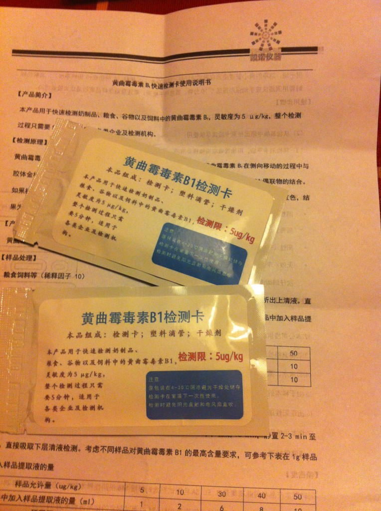
淘宝上购买的检测试纸

image

根据说明,要求10ml水,配5ml油,但是因为没有适合的容积工具,只好使用台秤来粗略的测量

image_1_

摇晃震荡15分钟,然后静置一段
image_2_

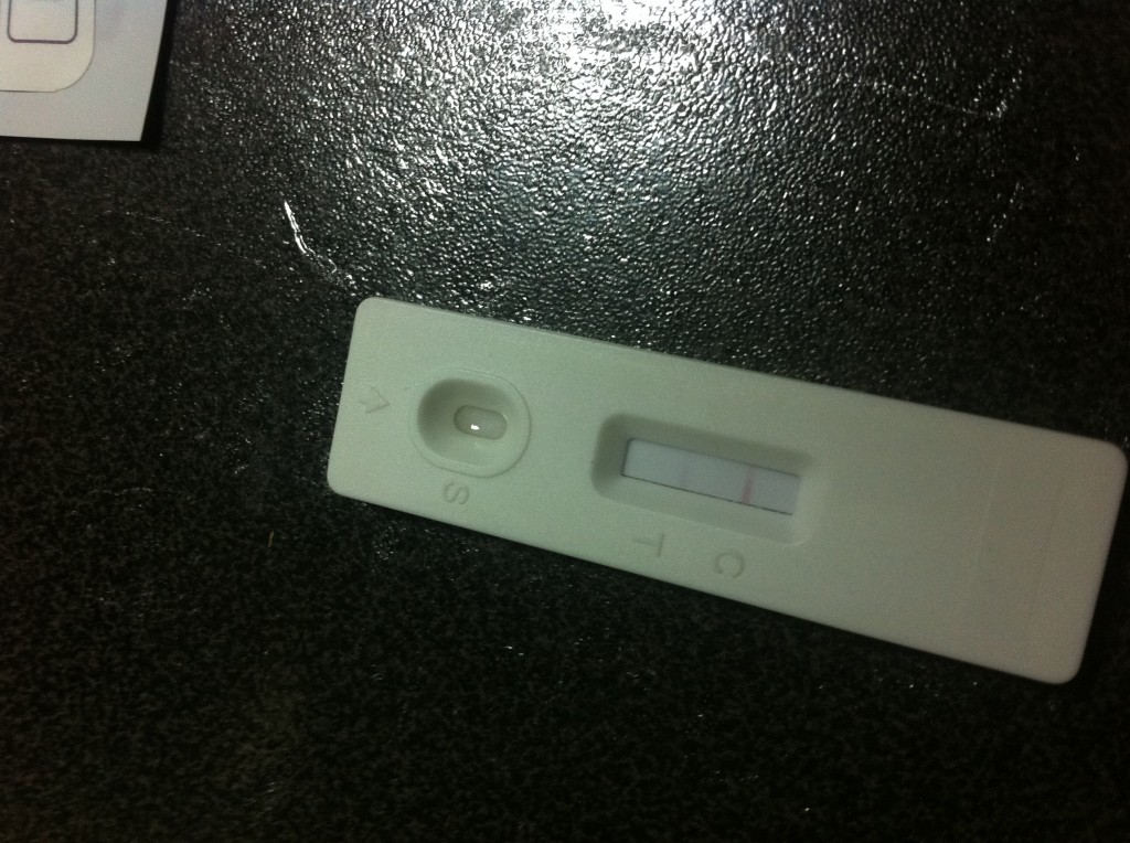
滴入到检测卡上,过一段时间之后查看结果,正常,检测合格
image_3_

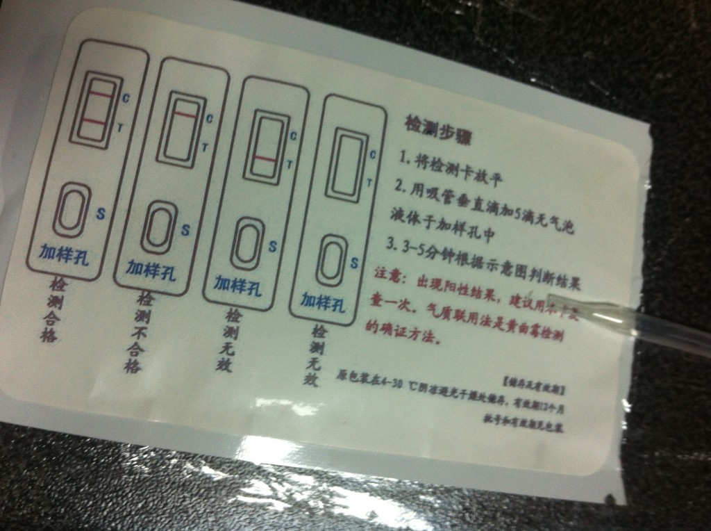
测试卡背面的比对说明
image_5_

参考:
1.http://baike.baidu.com/view/287205.htm?fr=aladdin

UDK2014 发布了

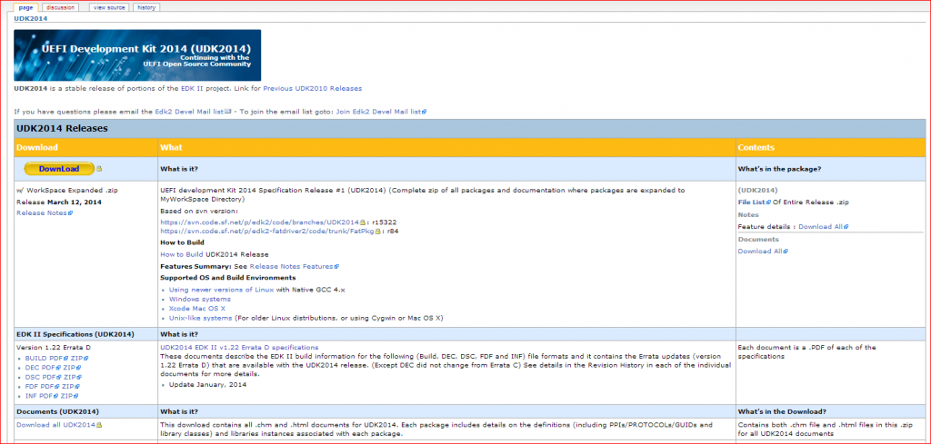
今天刚刚注意到 UDK2014 发布了,可以在下面的网址看到

http://sourceforge.net/apps/mediawiki/tianocore/index.php?title=UDK2014

udk2014

从 Release Note 来看,和UDK2010相比变化不大,有如下变化

1. Support Unified Extensible Firmware(UEFI) specification 2.4.
2. Support Platform Initialization(PI) specification 1.3.
3. Support OpenSSL version 0.98w and whole X509v3 extension check.
4. Support TPM 2.0.
5. Support I2C. //这个主要是平板用的
6. Support NVM Express.
7. Update ACPI5.0 tables, PCI definitions and Atapi definitions.
8. Update BaseTools Python version to 2.7.3.

用前一段写的计算频率的程序测试了一下,能够正常编译和运行。

更换ETS3125i电话机的电池

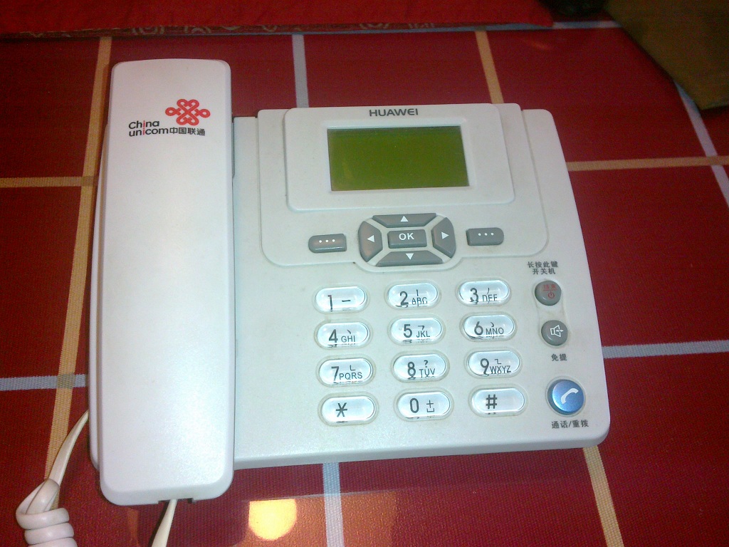
家里使用的无线电话用了几年之后感觉电池很差了,经常通话没有多久就自动关机了。taobao出售的电池要30元左右,于是自己动手更换新电池。20140501895

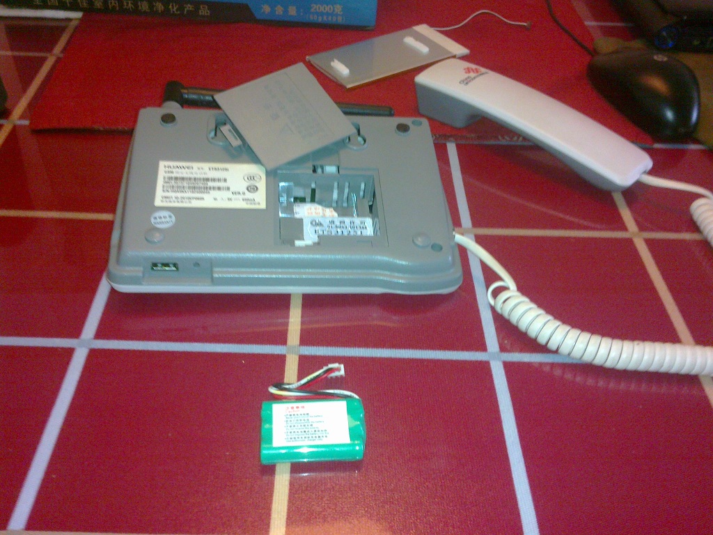
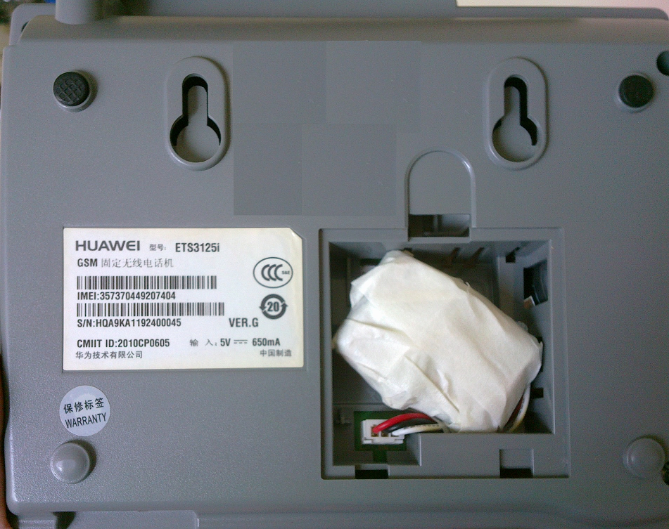
电池就在后盖里面,很好拆。20140501896

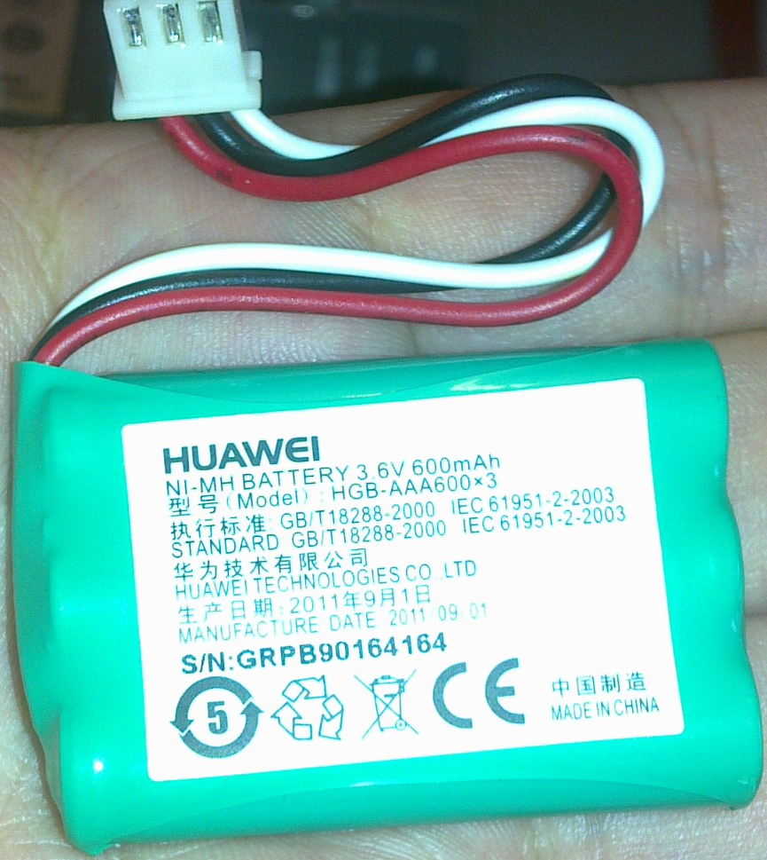
容量比较小,我现在也没有搞清楚,是一节600mah,还是三节加在一起600mah.font

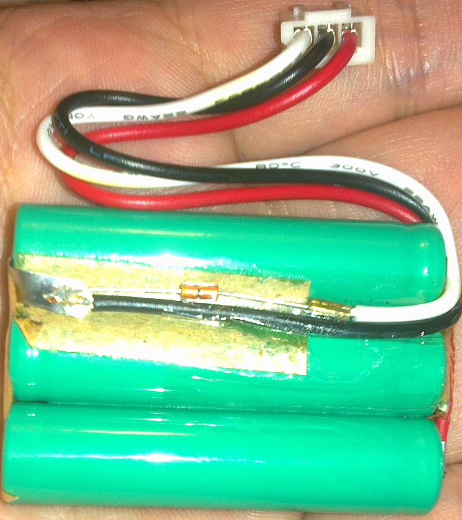
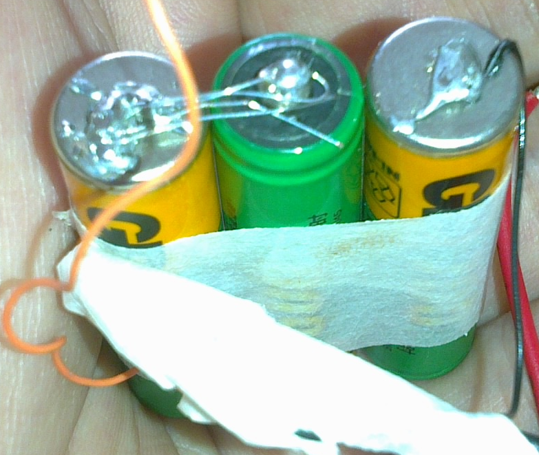
三节串联,构成的电池。引出了三根线,正极负极还有一个多余的白色Pin. 我请教了一下专门做电池的朋友,她们家的电池是用电阻做ID的,但是这个电池看起来中间的元件像是齐纳二极管,可能是用来做4.2v限压来测试是否充满的。

rear


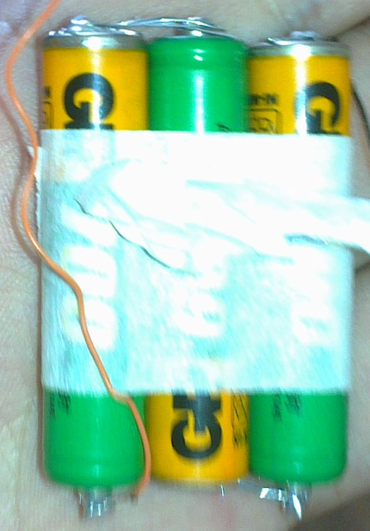
我找了3个普通的充电电池(7号的),串联起来。电极不吃锡,我用了一种网上买的点焊剂,蛮好用的。

kk

我是直接用之前电池的线路。负极出来一根线和那个白色的线是并联在一起的。

ss

包起来,装进去就好了。

end


前面两次使用的时候电量不太准,循环两次之后就OK了。个人感觉充满一次,至少能够维持通话1个多小时了。


制作一个PS2键盘记录器

这是一个能够记录PS2键盘发出的按键信息的演示装置。

使用的元件:

Arduino UNO                          一块
PS2 延长线(一端公头,一端母头)     一根
测试钩                               三根

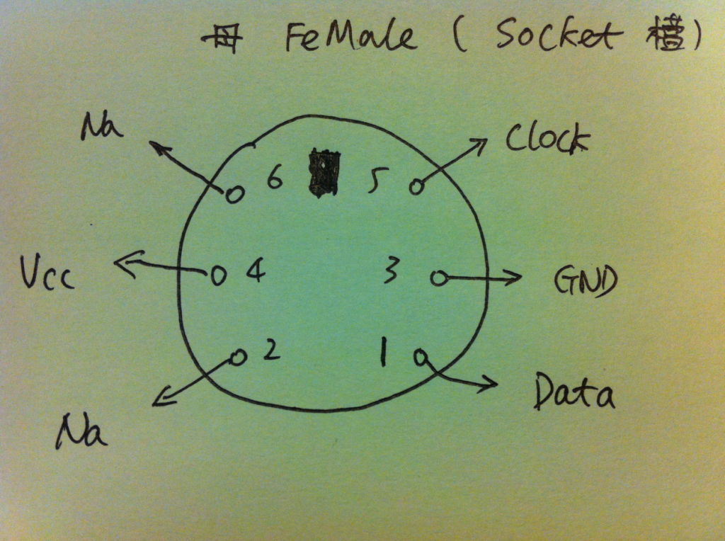
首先要将PS2延长线剥开,其中有四根线,分别是 Vcc/GND/Clock/Data。我们只需要钩取其中除了Vcc之外的三根线。

psa

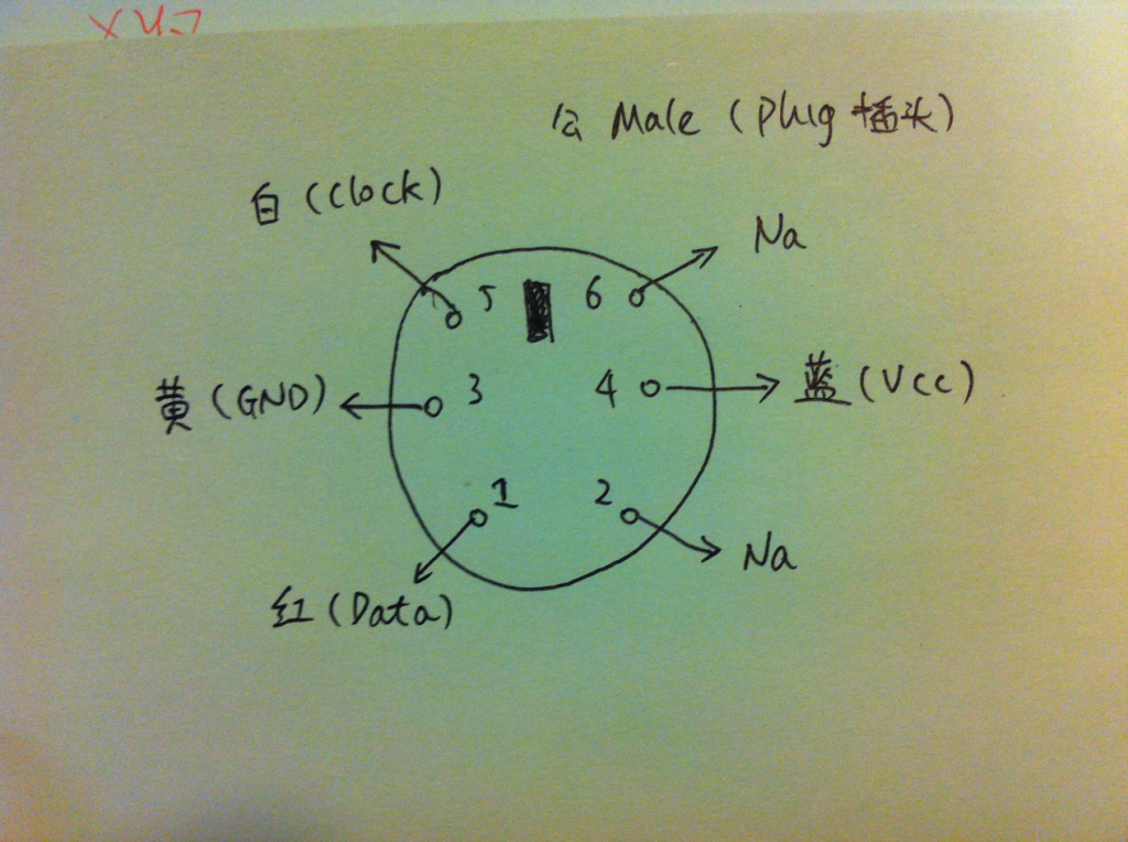
特别说一下这几根线的分布,在公头端和母头端看过去的Pin编号是对称的,如下图所示(网上有人说一些资料搞错了,我看了一下,是他本人搞错了公母而已)。选好线之后务必使用万用表确定接线无误。

psb

连接方面,上面图片中白色测试钩钩取的是黄色线 GND;绿色测试钩钩取的是红色Data;白色测试钩钩取的是白色线 Clock。

PS2 头和线色对应关系如下图:

psc

程序调用了PS2Keyboard library 【参考1】,用它来做PS2 协议的解码。调用的方式就是keyboard.begin(DataPin, IRQpin);  DataPin 要给出Arduino上连接到 PS2 Data的Pin脚;IRQpin 要给出Arduino上连接到 PS2 Clock的Pin脚。本例中,分别是 Pin8 和 Pin2。

psd

开始运行后, Setup()中会在串口输出一个菜单,提示如果输入 P ,那么会直接打印出 Arduino板载 EEPROM中的内容(UNO 的EEPROM不大,只有1K【参考2】。前面2个Byte用来存放一个记录当前要写入的位置。其余位置用来存储记录的键值。如果超过1K,那么返回开始处重新覆盖)。如果5秒之内没有输入 P ,那么程序会运行loop() 中的代码。先使用PS2Keyboard library 进行解码,然后每次都要从EEPROM中取出前2个Bytes组成一个指针,指示要将这个键值要存放在EEPROM中的位置。

  
#include "PS2Keyboard.h"
#include <EEPROM.h>

const int DataPin = 8;
const int IRQpin =  2;
const int MaxLength = 1024;
PS2Keyboard keyboard;
int SaveTo;

void setup() {
  boolean TimeOutMark=true;
  keyboard.begin(DataPin, IRQpin);  
  Serial.begin(9600);
  
  Serial.write("Keyboard Logger for Arduino\n");
  Serial.write("www.lab-z.com 2014.5\n");
  Serial.write("   p - for output record \n");
  
  unsigned long _time = millis();  //用于超时
  while ((millis() - _time) < 5000)
  {
  char inChar = Serial.read();
  if ((inChar == 'p') || (inChar == 'P'))
    {
       TimeOutMark=false;
       for (int i=2; i<MaxLength; i++)
         {
              char c = EEPROM.read(i) ;
              // check for some of the special keys
              if (c == PS2_ENTER) {
                    Serial.println();
              } else if (c == PS2_TAB) {
                    Serial.print("[Tab]");
              } else if (c == PS2_ESC) {
                    Serial.print("[ESC]");
              } else if (c == PS2_PAGEDOWN) {
                    Serial.print("[PgDn]");
              } else if (c == PS2_PAGEUP) {
                    Serial.print("[PgUp]");
              } else if (c == PS2_LEFTARROW) {
                    Serial.print("[Left]");
              } else if (c == PS2_RIGHTARROW) {
                    Serial.print("[Right]");
              } else if (c == PS2_UPARROW) {
                    Serial.print("[Up]");
              } else if (c == PS2_DOWNARROW) {
                    Serial.print("[Down]");
              } else if (c == PS2_DELETE) {
                    Serial.print("[Del]");
              } else {
                  // otherwise, just print all normal characters
                    Serial.print(c);
              } // End of else            
         }//End of for
     } //End of if ((inChar = 'p') || (inChar = 'P'))  
  }// End of While 
 if (TimeOutMark==true)  {Serial.write("Timeout occured!\n");  }
 else {Serial.write('\n Output End!');}
 
    EEPROM.write(0,2);
    EEPROM.write(1,0);     

} // End of Setup

void loop() {
  char c;

 if (keyboard.available()) {
     // read the next key
    c = keyboard.read();
   Serial.print(c);
    SaveTo = EEPROM.read(0) + (EEPROM.read(1) <<8);
    EEPROM.write(SaveTo,c);
    SaveTo++;
    if (SaveTo>MaxLength) {SaveTo=2;}
    EEPROM.write(0,SaveTo);
    EEPROM.write(1,(SaveTo >> 8));    
  }

  
}


实验中使用的是一个USB键盘,通过USB转PS2转为电脑上能使用的PS2 (资料上说现在的USB键盘内置2种协议,根据当前插入的接口自动选择输出的协议)。该键盘通过上面提到的PS2延长线接入电脑。记录结果如下:

pse

因为尺寸的原因,可以看出来这个东西只有演示的价值,如果真想做一个实用性的东西,还要选择PIC系列的小尺寸单片机加上SPI ROM………

下载
KeyLog

参考:

1.http://playground.arduino.cc/Main/PS2Keyboard

2.Arduino上的单片机自带EEPROM  328P 有 1024字节

http://wiki.geek-workshop.com/doku.php?do=export_xhtml&id=arduino:libraries:eeprom

直接测量电机转速

论坛上有个朋友提了一个问题【参考 1】 “请问大神,我想测一个上万转的转速,也就是几万hz的频率,应该用什么传感器?”

论坛上的朋友介绍说这样的通常都是用减速齿轮,降低到一个可以直接测量的范围后进行测试。但是我认为这样做比较麻烦,需要适合的减速齿轮,并且可能导致测不准的问题。我猜测应该可以使用光敏电阻加激光同,通过轴承上的小孔对光遮断和导通来完成测试,

为了验证这个想法,设计了一个简单的装置,使用了如下的元件:

1.光敏电阻(我不知道是什么材料)

2.激光头(很早之前买东西送的,功率应该是非常小的)

3.电动机(1v-6V)

4.100K 电阻一只

设备:

数字示波器一台(泰克的)

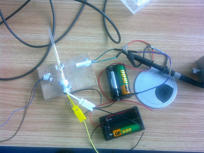
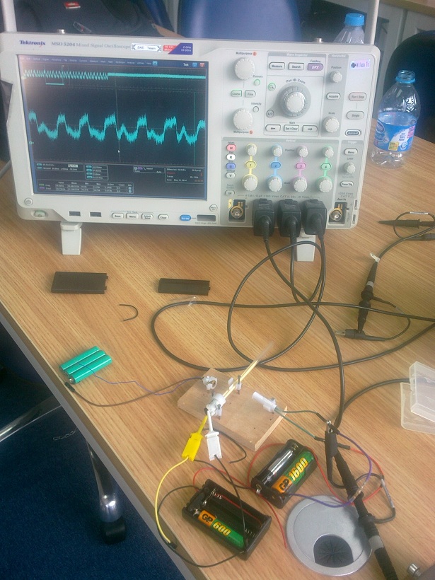
下图可以看到,用了3组电池供电,最左边是激光头 3.7v左右,中间黄色和白色夹子是给电机供电的,分别测试是 1.5 3v 和 4.5v供电最右边是和一个100K电阻串联的光敏电阻,我做了一个小纸筒包起来了,这样可以减少外界光线的干扰。转轴是一根塑料吸管,里面插入了4根牙签,这样刚好能将电机的轴卡住。同时,轴上还有一张纸片,这样转动起来之后可以阻断激光。

20140512916

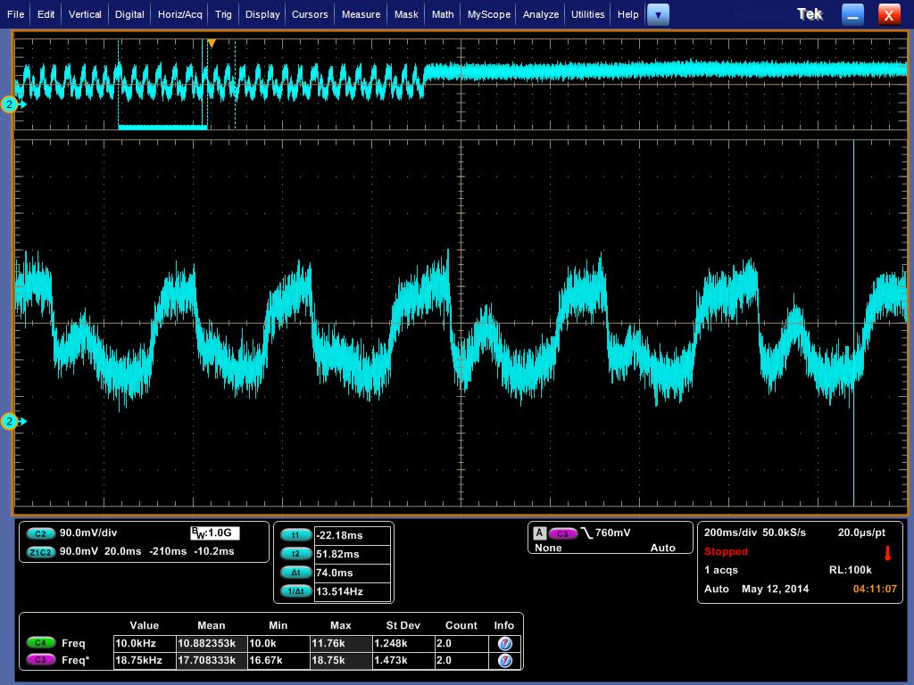
测试结果如下,这是电动机使用 1.5v 供电时,测试的结果:

140512_041048

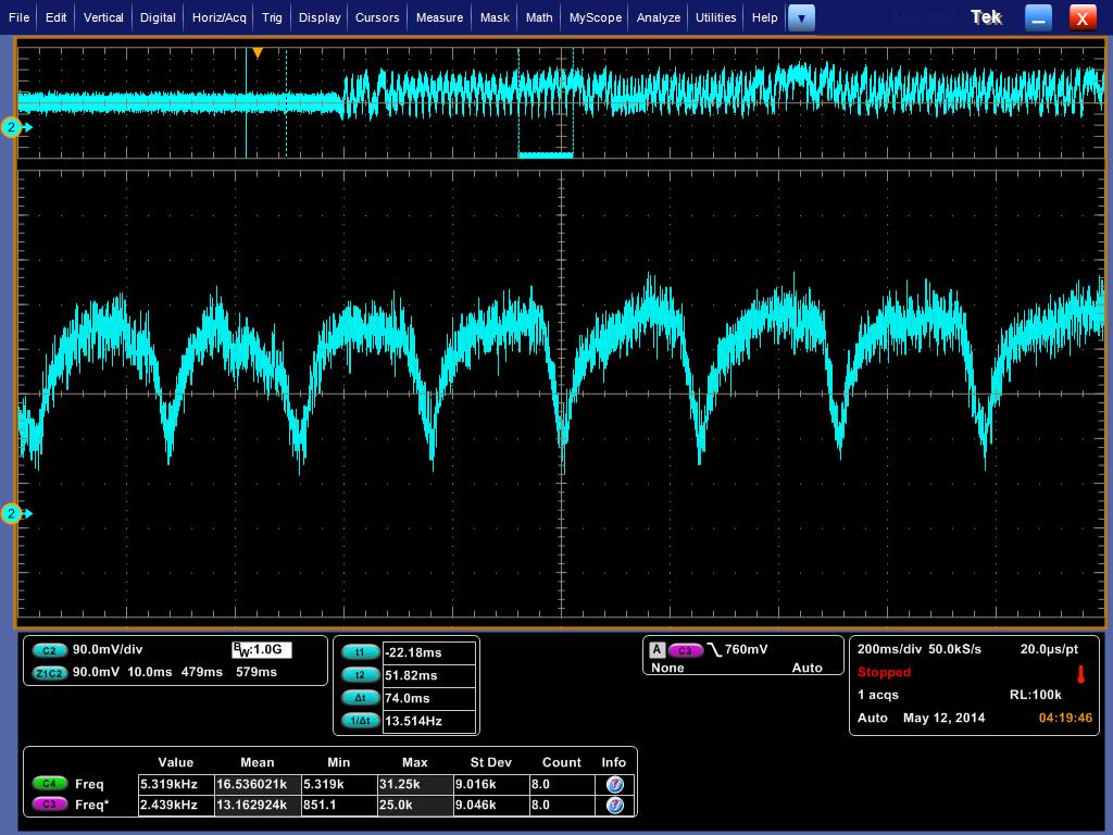
这是电动机使用 4.5v 供电时,测试的结果:

140512_041946

可以从波形,结合遮蔽的原理可以很容易计算出频率。但是对于波形为什么会有这么大的差别我并没有太好的解释,猜测是因为电压不同导致扭力的差别导致的,可以看出来当4.5v时是更接近理论波形的。

最后放一张overview的照片。

20140512917

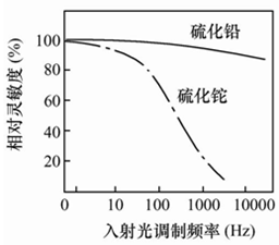
从理论上说,我设想的直接用激光来进行转速测试是可行的。但是目前的资料来看选择硫化铅的光敏电阻应该是可行的。【参考2】

hz

参考:

1.http://www.geek-workshop.com/thread-9612-1-1.html

2.https://www.google.com.hk/url?sa=t&rct=j&q=&esrc=s&source=web&cd=11&ved=0CCkQFjAAOAo&url=%68%74%74%70%3a%2f%2f%64%6f%63%73%65%72%76%69%63%65%2e%73%68%74%76%75%2e%6f%72%67%2e%63%6e%2f%77%65%62%2f%64%6f%77%6e%6c%6f%61%64%2e%61%73%70%78%3f%46%69%6c%65%49%44%3d%35%30%61%36%32%66%62%36%2d%31%33%66%33%2d%34%66%30%39%2d%38%32%66%66%2d%62%30%32%33%31%30%33%37%34%65%31%31&ei=aWt3U9fXI9eC8gX714LoCg&usg=AFQjCNG73nRZfEuQ_6yCAEzLGo7VjaUmHA&sig2=bBUADuiJCdukBOP-BJl49g
光敏电阻的频率特性

关于 Arduino Serial Print 和 Write 的一点认识

https://github.com/arduino/Arduino/blob/master/hardware/arduino/cores/arduino/HardwareSerial.h

class HardwareSerial : public Stream
{
private:
ring_buffer *_rx_buffer;
ring_buffer *_tx_buffer;
volatile uint8_t *_ubrrh;
volatile uint8_t *_ubrrl;
volatile uint8_t *_ucsra;
volatile uint8_t *_ucsrb;
volatile uint8_t *_ucsrc;
volatile uint8_t *_udr;
uint8_t _rxen;
uint8_t _txen;
uint8_t _rxcie;
uint8_t _udrie;
uint8_t _u2x;
bool transmitting;
public:
HardwareSerial(ring_buffer *rx_buffer, ring_buffer *tx_buffer,
volatile uint8_t *ubrrh, volatile uint8_t *ubrrl,
volatile uint8_t *ucsra, volatile uint8_t *ucsrb,
volatile uint8_t *ucsrc, volatile uint8_t *udr,
uint8_t rxen, uint8_t txen, uint8_t rxcie, uint8_t udrie, uint8_t u2x);
void begin(unsigned long);
void begin(unsigned long, uint8_t);
void end();
virtual int available(void);
virtual int peek(void);
virtual int read(void);
virtual void flush(void);
virtual size_t write(uint8_t);
inline size_t write(unsigned long n) { return write((uint8_t)n); }
inline size_t write(long n) { return write((uint8_t)n); }
inline size_t write(unsigned int n) { return write((uint8_t)n); }
inline size_t write(int n) { return write((uint8_t)n); }
using Print::write; // pull in write(str) and write(buf, size) from Print
operator bool();
};

https://github.com/arduino/Arduino/blob/master/hardware/arduino/cores/arduino/HardwareSerial.cpp

size_t HardwareSerial::write(uint8_t c)
{
int i = (_tx_buffer->head + 1) % SERIAL_BUFFER_SIZE;

// If the output buffer is full, there’s nothing for it other than to
// wait for the interrupt handler to empty it a bit
// ???: return 0 here instead?
while (i == _tx_buffer->tail)
;

_tx_buffer->buffer[_tx_buffer->head] = c;
_tx_buffer->head = i;

sbi(*_ucsrb, _udrie);
// clear the TXC bit — “can be cleared by writing a one to its bit location”
transmitting = true;
sbi(*_ucsra, TXC0);

return 1;
}

从上面可以看出来 Serial.Write 是直接把要发的东西送出去,Serial.Print 就复杂多了,会占用大量的内存。因此,如果有可能尽量用 Serial.Write。 如果你的程序用的大量的 Serial.Print,并且出现奇怪的问题,很可能产生的原因是内存不足,不妨删除几个 Print试试。

编译和使用 SpbTestTool

SpbTestTool 是 Windows WDK Sample 中的一个代码【参考1】,页面上介绍如下

The SpbTestTool sample serves two purposes. First, it demonstrates how to open a handle to the SPB controller, use the SPB interface from a KMDF driver, and employ GPIO passive-level interrupts. Second, it implements a set of commands for communicating with a peripheral device to aid in debugging.

程序本身实际上是两部分:一个是SYS的Demo Code (通过I2C访问设备的驱动)。这个SYS使用了 I2C 的资源以及GPIO;另一个是Application,演示如何通过应用程序调用驱动来完成通讯。

编译环境是 VS2013+WDK (8.1的),这也是MS推荐开发Win8.1 Driver使用的。正常情况下,安装完成之后,直接打开 MS 的Sample就可以直接编译成功,不需要额外的设置。如果无法编译,请检查VS2013和WDK 的安装顺序,需要先装VS再装WDK。具体环境的搭建住在这里就不再赘述了。

测试编译正常之后,就可以打开 SpbTestTool 这个工程文件了。

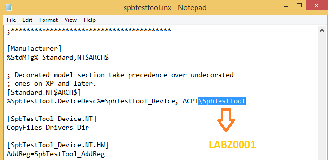
需要修改SpbTestTool.inx文件,这里面给出了编译后生成的INF文件中的 ACPI ID,需要和你BIOS中的一致。默认值是 SpbTestTool。如果你在ASL中真的使用这个,会发现BIOS的编译都无法通过。

labz1

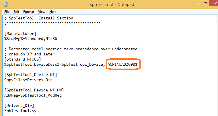
修改了上面的文件后,每次编译生成的inf文件就是下面这个样子

labz2

同时,你BIOS中的ASL要写成下面的样子

Device(LABZ)
{
	Name(_ADR, 0x0)
	Name(_HID, "LABZ0001")
	Name(_CID, "LABZ0001")
	Name(_UID, 0x1)

	Method(_STA, 0x0, NotSerialized)
		{
			return(0x0f)
		}
			
	Method(_CRS, 0x0, NotSerialized)
		{
			Name(ZBUF,ResourceTemplate () {
					I2CSerialBus(0x50,          //SlaveAddress: bus address
						,                       //SlaveMode: default to ControllerInitiated
						400000,                 //ConnectionSpeed: in Hz
						,						//Addressing Mode: default to 7 bit
						"\\_SB.I2C3",           //ResourceSource: I2C bus controller name
						,                       //Descriptor Name: creates name for offset of resource descriptor
						)  //VendorData
					GpioInt(LEVEL,  ActiveLow, Exclusive, PullDown, 0, "\\_SB.GPO2", ) {6}//SAR INT  (GPIO INT)
				})
			Return (ZBUF)
		}
}// Device LABZ


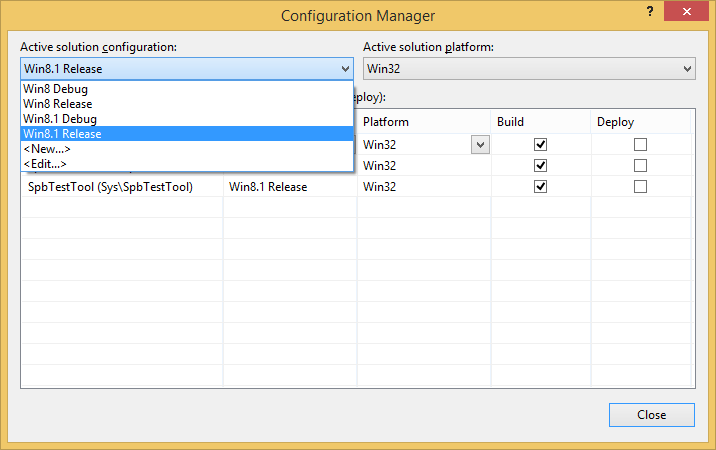
编译时还需要在菜单 Build -> Configuration Manager 下,选择 Win8.1 Release。具体原因后面说。

Untitled3

编译完成后,把所有的东西一股脑 copy 到U盘上。

编译BIOS,之后将生成的BIOS刷新到被测机上。启动进入系统之后,设备管理中应该会出现我们在ASL中设置的这个设备,ID是我们刚才设置的 LABZ0001.

Capture3

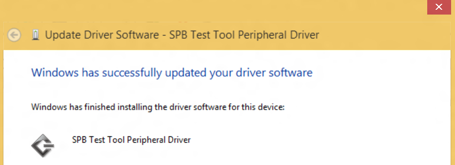
下面是安装驱动。因为我们的驱动没有签名,所以要保证已经关闭签名验证之类的设置。

Capture4

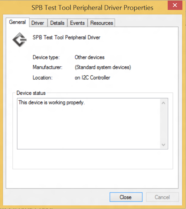
安装后的样子

Capture5

Capture6

驱动的编译和安装到此已经结束,接下来就可以进行测试了。

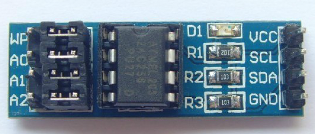
测试需要有硬件对应,我这里选择的是一款I2C接口的EEPROM

eeprom

引脚对应连接到板子上的I2C即可,需要注意的是,可以选择 1.8V或者3.3V 供电都可以,差别在于如果选择前者的话,通讯速度上只能选择100KHz,选择后者之后速度可以选择 400KHz,这个数据来自 AT24C256 的DataSheet【参考 2】。

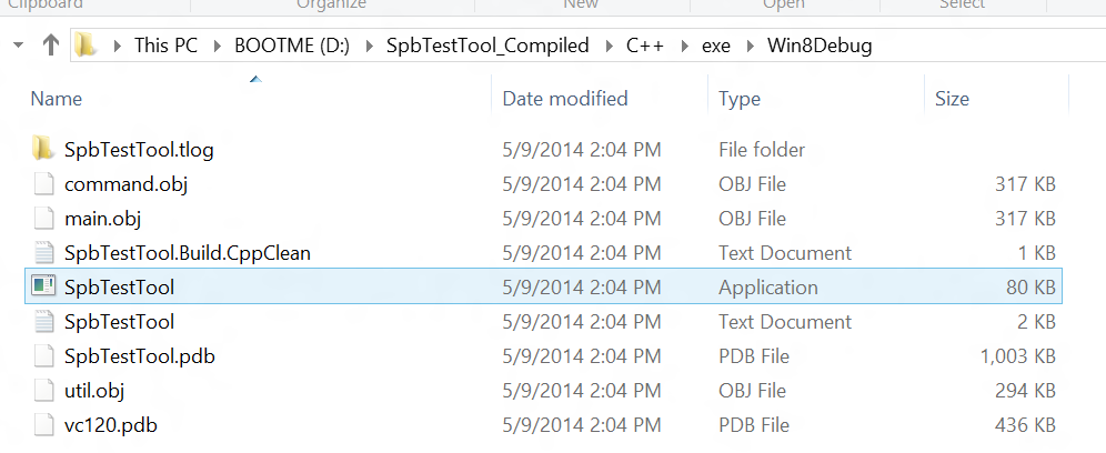
编译后的可执行文件在下面这个位置

Capture8

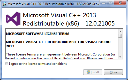
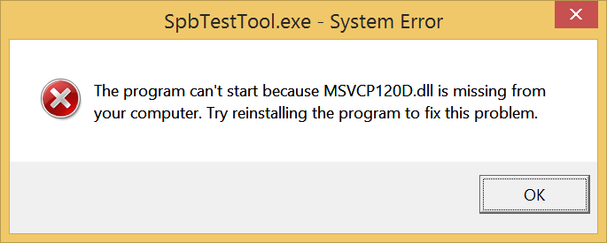
因为是VS2013编译的,所以在运行的时候需要对应的DLL库的支持,如果你的Win8.1没有的话,请到网上下载 vcredist_x86.exe

rb2013

如果你看到下面的画面,那么是因为你没有选择 Release Build

capa

运行之后,程序是命令行方式。使用 h 可以看到帮助。

我们的目标是:在EEPROM中,从 0 开始保存 1 2 3 这三个值,

首先,要打开设备,命令是 open

open

然后是写入命令可以写为 write {0 0 1 2 3} (前面 0 0 是一个16位的地址 0x0000. 不要按照MS的说明写,它程序不支持 01 02 这样的写法)

接下来,是读EEPROM的命令 writeread {0 0 } 3 (意思是从 0 0 开始连续读3个)

Captured

因为EEPROM断电不会丢失数据,写入之后,你再关机重启,重新使用这个应用程序用命令读取,仍然能看到你写入的值。

参考:

1. Dev Center – Hardware > Samples > Windows Driver Kit (WDK) 8.1 Samples > SpbTestTool
http://code.msdn.microsoft.com/windowshardware/SpbTestTool-adda6d71
(另外,在完整的 WDK8.1 的Sample Package中,也有 SpbTestTool 这个程序,只是页面单独下载的要比完整Package中的新一些。建议直接下载单独页面提供的。)

备份一个: SpbTestTool

2. AT24C256 的 Datasheet at24c256

指定过程变量i用寄存器的问题

Pmason_rose 问我“VC中强制一个过程中变量i使用ebx咋写”?

VC2008下面先写一个简单的程序

#include "stdafx.h"

int _tmain(int argc, _TCHAR* argv[])
{
int i;

for (i=0;i<10;i++)
{
printf("%d: www.lab-z.com\n",i);
}
getchar();
return 0;
}

确定上面的程序可以正常编译通过之后,可以设置 Assembler Output 中,让VC2008直接输出机器码和汇编代码:

forcereg


在 Debug目录下会出现 loop.cod,内容如下,可以看出使用内存变量 i 做的循环

	ff		 lea	 edi, DWORD PTR [ebp-204]
  00012	b9 33 00 00 00	 mov	 ecx, 51			; 00000033H
  00017	b8 cc cc cc cc	 mov	 eax, -858993460		; ccccccccH
  0001c	f3 ab		 rep stosd

; 9    : 	int i;
; 10   : 
; 11   : 	for (i=0;i<10;i++)

  0001e	c7 45 f8 00 00
	00 00		 mov	 DWORD PTR _i$[ebp], 0
  00025	eb 09		 jmp	 SHORT $LN3@wmain
$LN2@wmain:
  00027	8b 45 f8	 mov	 eax, DWORD PTR _i$[ebp]
  0002a	83 c0 01	 add	 eax, 1
  0002d	89 45 f8	 mov	 DWORD PTR _i$[ebp], eax
$LN3@wmain:
  00030	83 7d f8 0a	 cmp	 DWORD PTR _i$[ebp], 10	; 0000000aH
  00034	7d 1d		 jge	 SHORT $LN1@wmain

; 12   : 	{
; 13   : 		printf("%d: www.lab-z.com\n",i);

  00036	8b f4		 mov	 esi, esp
  00038	8b 45 f8	 mov	 eax, DWORD PTR _i$[ebp]
  0003b	50		 push	 eax
  0003c	68 00 00 00 00	 push	 OFFSET ??_C@_0BD@OPIHGHME@?$CFd?3?5www?4lab?9z?4com?6?$AA@
  00041	ff 15 00 00 00
	00		 call	 DWORD PTR __imp__printf
  00047	83 c4 08	 add	 esp, 8
  0004a	3b f4		 cmp	 esi, esp
  0004c	e8 00 00 00 00	 call	 __RTC_CheckEsp

; 14   : 	}

  00051	eb d4		 jmp	 SHORT $LN2@wmain
$LN1@wmain:

首先,使用寄存器变量试试,用register 关键字修饰 Int i; 修改程序

#include "stdafx.h"

int _tmain(int argc, _TCHAR* argv[])
{
	register int i;

	for (i=0;i<10;i++)
	{
		printf("%d: www.lab-z.com\n",i);
	}
	getchar();
	return 0;
}

查看结果

; 9    : 	register int i;
; 10   : 
; 11   : 	for (i=0;i<10;i++)

  0001e	c7 45 f8 00 00
	00 00		 mov	 DWORD PTR _i$[ebp], 0
  00025	eb 09		 jmp	 SHORT $LN3@wmain
$LN2@wmain:
  00027	8b 45 f8	 mov	 eax, DWORD PTR _i$[ebp]
  0002a	83 c0 01	 add	 eax, 1
  0002d	89 45 f8	 mov	 DWORD PTR _i$[ebp], eax
$LN3@wmain:
  00030	83 7d f8 0a	 cmp	 DWORD PTR _i$[ebp], 10	; 0000000aH
  00034	7d 1d		 jge	 SHORT $LN1@wmain

; 12   : 	{
; 13   : 		printf("%d: www.lab-z.com\n",i);

  00036	8b f4		 mov	 esi, esp
  00038	8b 45 f8	 mov	 eax, DWORD PTR _i$[ebp]
  0003b	50		 push	 eax
  0003c	68 00 00 00 00	 push	 OFFSET ??_C@_0BD@OPIHGHME@?$CFd?3?5www?4lab?9z?4com?6?$AA@
  00041	ff 15 00 00 00
	00		 call	 DWORD PTR __imp__printf
  00047	83 c4 08	 add	 esp, 8
  0004a	3b f4		 cmp	 esi, esp
  0004c	e8 00 00 00 00	 call	 __RTC_CheckEsp

; 14   : 	}

  00051	eb d4		 jmp	 SHORT $LN2@wmain

恩就是说编译器根本没有鸟我…..查看资料:

“声明为register类型的变量提示计算机这个变量应该存储于机器的硬件寄存器而不是内存中。通常,寄存器变量比存于内存中的变量访问起来效率更高。但是,编译器并不一定要理睬register关键字,如果有太多的变量被声明为register类型,那么编译器只选取前几个,将其实际存储于寄存器中,其余的就按普通变量处理。如果一个编译器自己具有一套寄存器优化方案的话,它也可能忽略register关键字,其依据是由编译器决定哪些变量春处于寄…”【参考1】

还有其他办法,就是直接插入汇编语言。修改程序如下:

// loop.cpp : Defines the entry point for the console application.
//

#include "stdafx.h"

int _tmain(int argc, _TCHAR* argv[])
{
	int i;

__asm        
{   
	mov	ebx,0
next:
    push ebx
	mov i,ebx
} 
		printf("%d: www.lab-z.com\n",i);
__asm        
{	
	pop	ebx
    inc ebx
    cmp ebx,10
	jNz	next
} 

	getchar();
	return 0;
}

运行结果和之前的程序完全一样,对应的汇编和机器码

; 9    : 	int i;
; 10   : 
; 11   : __asm        
; 12   : {   
; 13   : 	mov	ebx,0

  0001e	bb 00 00 00 00	 mov	 ebx, 0
$next$5245:

; 14   : next:
; 15   :     push ebx

  00023	53		 push	 ebx

; 16   : 	mov i,ebx

  00024	89 5d f8	 mov	 DWORD PTR _i$[ebp], ebx

; 17   : } 
; 18   : 		printf("%d: www.lab-z.com\n",i);

  00027	8b f4		 mov	 esi, esp
  00029	8b 45 f8	 mov	 eax, DWORD PTR _i$[ebp]
  0002c	50		 push	 eax
  0002d	68 00 00 00 00	 push	 OFFSET ??_C@_0BD@OPIHGHME@?$CFd?3?5www?4lab?9z?4com?6?$AA@
  00032	ff 15 00 00 00
	00		 call	 DWORD PTR __imp__printf
  00038	83 c4 08	 add	 esp, 8
  0003b	3b f4		 cmp	 esi, esp
  0003d	e8 00 00 00 00	 call	 __RTC_CheckEsp

; 19   : __asm        
; 20   : {	
; 21   : 	pop	ebx

  00042	5b		 pop	 ebx

; 22   :     inc ebx

  00043	43		 inc	 ebx

; 23   :     cmp ebx,10

  00044	83 fb 0a	 cmp	 ebx, 10			; 0000000aH

; 24   : 	jNz	next

  00047	75 da		 jne	 SHORT $next$5245

; 25   : }

因此,直接嵌入汇编是一个很好的解决方法。需要注意的是堆栈的平衡以及在复杂的数据结构和操作的情况下一定要保证不能干扰参数传递。

参考1:http://bbs.csdn.net/topics/300225947