pmason_rose 改造的遥控小车

两年前,再次学习单片机,此次入手的单片机比它的爹妈强多了。不仅把rs232接口用usb硬连接到pc而且直接写其rom!(本人不是硬件专业人士先进东西见的少)。琢磨着做个啥当学习目标呢,做个pc控制的小车吧。首先得解决mcu对数据的处理,恩,定义个包头aa55加个数据长度字0xh加个命令字0xh,再加上数据字。差资料显示状态机方式处理最好。写完后写上位程序。嘿嘿masm32是我的最爱,不过3天调试成功!为了增加可玩性,哈加入tcp方式传输命令流。一切调试ok,接上小车,呵呵大告成功!上传视频共同分享快乐!

pmason_rose 联系方式 pmason_rose@qq.com(332779423)

Step to UEFI (22) —– Application的入口分析

研究一下:UEFI APP 在编译的时候会加入什么头。

使用上一次的示例程序 ClrTest。稍微修改一下,去掉清屏的调用以便我们能看清结果:

#include <Uefi.h>
#include <Library/UefiLib.h>
#include <Library/ShellLib.h>
#include <Library/UefiApplicationEntryPoint.h>

extern EFI_BOOT_SERVICES             	 *gBS;
extern EFI_SYSTEM_TABLE			 *gST;
extern EFI_RUNTIME_SERVICES 		 *gRT;

//
// Entry point function 
//
EFI_STATUS
UefiMain (
  IN EFI_HANDLE        ImageHandle,
  IN EFI_SYSTEM_TABLE  *SystemTable
  )
{
   Print(L"www.lab-z.com\n");
   return EFI_SUCCESS;
}

编译命令是 build -p AppPkg\AppPkg.dsc

首先查看生成的 Makefile

在 \Build\AppPkg\DEBUG_VS2008\IA32\AppPkg\Applications\ClsTest\ClsTest\Makefile

下面的语句指定了入口函数

DLINK_FLAGS = /NOLOGO /NODEFAULTLIB /IGNORE:4001 /OPT:REF /OPT:ICF=10 /MAP
/ALIGN:32 /SECTION:.xdata,D /SECTION:.pdata,D /MACHINE:X86 /LTCG /DLL
/ENTRY:$(IMAGE_ENTRY_POINT) /SUBSYSTEM:EFI_BOOT_SERVICE_DRIVER /SAFESEH:NO
/BASE:0 /DRIVER /DEBUG

同样的 Makefile中,给出入口函数

IMAGE_ENTRY_POINT = _ModuleEntryPoint

顺便看一眼 \Build\AppPkg\DEBUG_VS2008\IA32\AppPkg\Applications\ClsTest\ClsTest\OUTPUT\ClsTest.map

__ModuleEntryPoint 00000260 f UefiApplicationEntryPoint:ApplicationEntryPoint.obj

就是说 ModuleEntryPoint 是从 ApplicationEntryPoint.obj 中链接进来的

这个函数的头文件在 \MdePkg\Include\Library\UefiApplicationEntryPoint.h

再进一步查找 \MdePkg\Library\UefiApplicationEntryPoint\UefiApplicationEntryPoint.inf 其中给出了对应的函数体的位置

[Sources]
ApplicationEntryPoint.c

打开看看 \MdePkg\Library\UefiApplicationEntryPoint\ApplicationEntryPoint.c

EFI_STATUS
EFIAPI
_ModuleEntryPoint (
IN EFI_HANDLE ImageHandle,
IN EFI_SYSTEM_TABLE *SystemTable
)
...............
//
// Call constructor for all libraries.
//
ProcessLibraryConstructorList (ImageHandle, SystemTable);
//
// Call the module's entry point
//
Status = ProcessModuleEntryPointList (ImageHandle, SystemTable);
//
// Process destructor for all libraries.
//
ProcessLibraryDestructorList (ImageHandle, SystemTable);

其中调用了4个函数,下面分别按图索骥

  1. ProcessLibraryConstructorList 函数,他在

\Build\AppPkg\DEBUG_VS2008\IA32\AppPkg\Applications\ClsTest\ClsTest\DEBUG\AutoGen.c

追进去,看一下

VOID
EFIAPI
ProcessLibraryConstructorList (
IN EFI_HANDLE ImageHandle,
IN EFI_SYSTEM_TABLE *SystemTable
)
{
EFI_STATUS Status;
Status = UefiBootServicesTableLibConstructor (ImageHandle, SystemTable);
ASSERT_EFI_ERROR (Status);
Status = UefiRuntimeServicesTableLibConstructor (ImageHandle,SystemTable);
ASSERT_EFI_ERROR (Status);
Status = UefiLibConstructor (ImageHandle, SystemTable);
ASSERT_EFI_ERROR (Status);
}


1.1 追一下UefiBootServicesTableLibConstructor  发现它在\MdePkg\Library\UefiBootServicesTableLib\UefiBootServicesTableLib.c

EFI_STATUS
EFIAPI
UefiBootServicesTableLibConstructor (
IN EFI_HANDLE ImageHandle,
IN EFI_SYSTEM_TABLE *SystemTable
)
{
//
// Cache the Image Handle
//
gImageHandle = ImageHandle;  //看到这里也能明白之前文章中Extern 的gImageHandle哪里来了
ASSERT (gImageHandle != NULL);
//
// Cache pointer to the EFI System Table
//
gST = SystemTable;
ASSERT (gST != NULL);

//
// Cache pointer to the EFI Boot Services Table
//
gBS = SystemTable->BootServices;
ASSERT (gBS != NULL);

return EFI_SUCCESS;
}


1.2   再看看UefiRuntimeServicesTableLibConstructor 在 \MdePkg\Library\UefiRuntimeServicesTableLib\UefiRuntimeServicesTableLib.c

EFI_STATUS
EFIAPI
UefiRuntimeServicesTableLibConstructor (
  IN EFI_HANDLE        ImageHandle,
  IN EFI_SYSTEM_TABLE  *SystemTable
  )
{
  //
  // Cache pointer to the EFI Runtime Services Table
  //
  gRT = SystemTable->RuntimeServices;
  ASSERT (gRT != NULL);
  return EFI_SUCCESS;
}


1.3   UefiLibConstructor  在\MdePkg\Library\UefiLib\UefiLib.c

EFI_STATUS
EFIAPI
UefiLibConstructor (
  IN EFI_HANDLE        ImageHandle,
  IN EFI_SYSTEM_TABLE  *SystemTable
  )
{
  return EFI_SUCCESS;
}


2. ProcessModuleEntryPointList在

\Build\AppPkg\DEBUG_VS2008\IA32\AppPkg\Applications\ClsTest\ClsTest\DEBUG\AutoGen.c

EFI_STATUS
EFIAPI
ProcessModuleEntryPointList (
IN EFI_HANDLE ImageHandle,
IN EFI_SYSTEM_TABLE *SystemTable
)
{
return UefiMain (ImageHandle, SystemTable); //至此,马上进入到了我们写的函数中
}


3.继续追ProcessLibraryDestructorList 这里应该是收尾的一些工作了

\Build\AppPkg\DEBUG_VS2008\IA32\AppPkg\Applications\ClsTest\ClsTest\DEBUG\AutoGen.c

VOID
EFIAPI
ProcessLibraryDestructorList (
  IN EFI_HANDLE        ImageHandle,
  IN EFI_SYSTEM_TABLE  *SystemTable
  )
{

}


上面很罗嗦的说了很多,总结一下可以用下面的图表示调用过程

AppEntry


当然,说了很多如果没有实验不能保证正确性

验证的办法是在上述提到的过程里面插入下面的语句

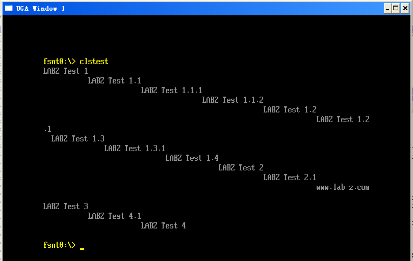
SystemTable->ConOut->OutputString(SystemTable->ConOut,L"LABZ Test X.X\n");

如果输出结果能够正常输出全部插入的,那么表示找到的点是正确的。

结果
appentry2

============================================================

2024年10月9日

还可以在 UefiApplicationEntryPoint.inf文件中加入如下编译指令:


[BuildOptions]
  MSFT:*_*_X64_CC_FLAGS  = /FAsc /Od
  

之后,可以在对应的 Application 的 Build 目录下看到生成的 .COD 文件中出现的代码。
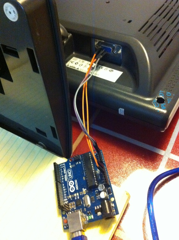
Arduino 读取显示器 EDID

arduinoedid

Arduinogetedid

Arduino2

文档对应代码

// SDA (20)  HDB15-12
// SCL (21)  HDB15-15
// +5V       HDB15-9
// GND       HDB15-5

#include <Wire.h>

const int i2c_port = 0x50;
byte buffer[BUFFER_LENGTH]; // 128 byte EEPROM data buffer

void setup() {
  Serial.begin(9600);
  Wire.begin();
  while (!Serial) 
    {;}
}

void loop() {
  Serial.println("(1) Read EDID and print.");
  Serial.println("(2) getInput()");
  Serial.println("(3) Item 3");
  Serial.println("");

  while (!Serial.available()) {;}

  switch (Serial.parseInt())
  {
      case 1: ddcRead(); break;
      case 2: getInput(); break;
      case 3: Serial.println("Item 3."); break;
      default: printError("Menu item does not exist.");
  }
  
  Serial.println("*************");
}

void printError(String message) {
  Serial.println("Error: " + message);
}

void ddcRead() {
  int blocks = 128 / BUFFER_LENGTH;
  
  Serial.println("Reading DDC...");
  
  Wire.beginTransmission(i2c_port);
  Wire.write(0);
  Wire.endTransmission(); 
 
  for (int block = 0; block < blocks; block += BUFFER_LENGTH) {
    Wire.requestFrom(i2c_port, BUFFER_LENGTH);
    for (int i = 0; i < BUFFER_LENGTH; i++) {
       //Serial.println(block + i, HEX);
       byte x = Wire.read();
       buffer[block + i] = x;
       //Serial.print(x, HEX); Serial.print(" ");
    }
  }
  Serial.println("Finished reading DDC.");
  printData();
}

void printData() {
  int rows = 128 / 16;
  for (int row = 0; row < rows; row++) {
    Serial.print(" ("); 
    if (row == 0) 
      Serial.print(0, HEX);
    Serial.print(row * 16, HEX); 
    Serial.print(") ");
    
    for (int half_col = 0; half_col < 2; half_col++) {
      for (int col = 0; col < 8; col++) {
        int index = (row * 16) + (half_col * 8) + col;
        byte b = buffer[index];
        if (b < 16) {
          Serial.print(0, HEX);
        }
        Serial.print(b, HEX);
        Serial.print(" ");
//        Serial.print("["); Serial.print(index, HEX); Serial.print("]");
      }
      
      if (half_col == 0) {
        Serial.print("- ");
      }
      else {
        Serial.println();
      }
    } 
  }
}

void getInput() {
  int input_buffer_len = 16;
  char input[input_buffer_len];
  Serial.println("Enter a string. 32 chars max. Input not echoed.");
  while (!Serial.available()) { ; }
  int input_len = Serial.readBytes(&input[0], input_buffer_len);
  Serial.print("Input is: ");
  for (int i = 0; i < input_len; i++) {
     Serial.write(input[i]); 
  }
  Serial.println(".");
  Serial.println("");
}

参考文档
I2C and Monitor DDC – Chrisbot

Step to UEFI (21) —– 清屏

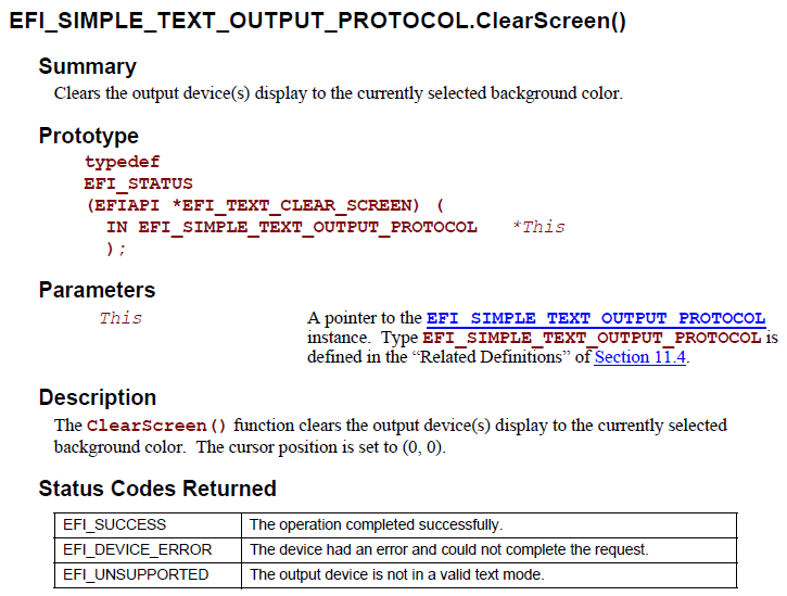
想实现一个清屏的功能,刚开始在CLIB中翻了半天没找到,用工具直接搜索了一下 clrscr (应该在 conio.h 中)压根儿没找到。估计是 CLIB没有支持,只好换个方法。想起来Syetem Table中有 EFI_SIMPLE_TEXT_OUTPUT_PROTOCOL 拿着SPEC翻了【参考1】一下,发现可以使用它的 ClearScreen 函数。

ClearScreen

写一个简单的程序验证之:

//
// ClearScreen
//
#include <Uefi.h>
#include <Library/UefiLib.h>
#include <Library/ShellLib.h>
#include <Library/UefiApplicationEntryPoint.h>

extern EFI_BOOT_SERVICES             	 *gBS;
extern EFI_SYSTEM_TABLE			 *gST;
extern EFI_RUNTIME_SERVICES 		 *gRT;

//
// Entry point function 
//
EFI_STATUS
UefiMain (
  IN EFI_HANDLE        ImageHandle,
  IN EFI_SYSTEM_TABLE  *SystemTable
  )
{
   INTN	i;

  for (i=0;i<1000;i++)
    {
	Print(L".");
    }
  Print(L".\n");

  gST -> ConOut -> SetAttribute(gST->ConOut,0x1);
  gST -> ConOut -> ClearScreen(gST->ConOut);
 
  //SystemTable ->ConOut ->ClearScreen(SystemTable ->ConOut);
  //Print(L"%lX\n",SystemTable ->ConOut ->ClearScreen);
  //Print(L"%lX\n",gST -> ConOut -> ClearScreen);
  //Print(L"%lX\n",gST->ConOut);
  return EFI_SUCCESS;
}


工作正常,能够清屏。

程序下载 ClsTest

参考:

1.UEFI Spec 2.4 P459

2.http://biosren.com/viewthread.php?tid=3050&highlight=clearscreen 关于SHELL下面修改(前)背景色

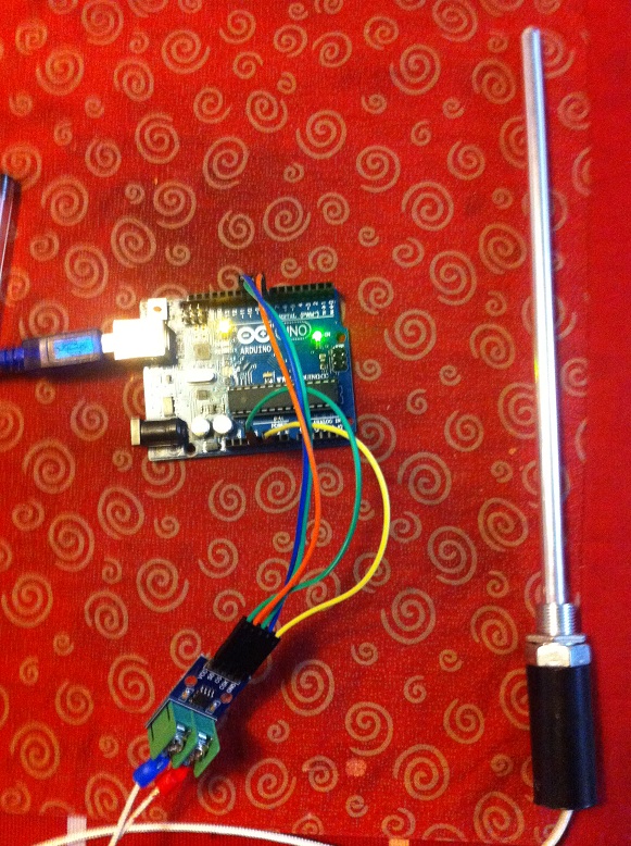
Max6675 热电偶

入手了一个热电偶温度传感器,这种东西是专门用来测试温度的,接触式的,具有测量范围大,精度高的特点。Taobao上搜索 “Arduino 热电偶”,卖家没有几个,我是从“圣源电子制作”的店铺卖的。

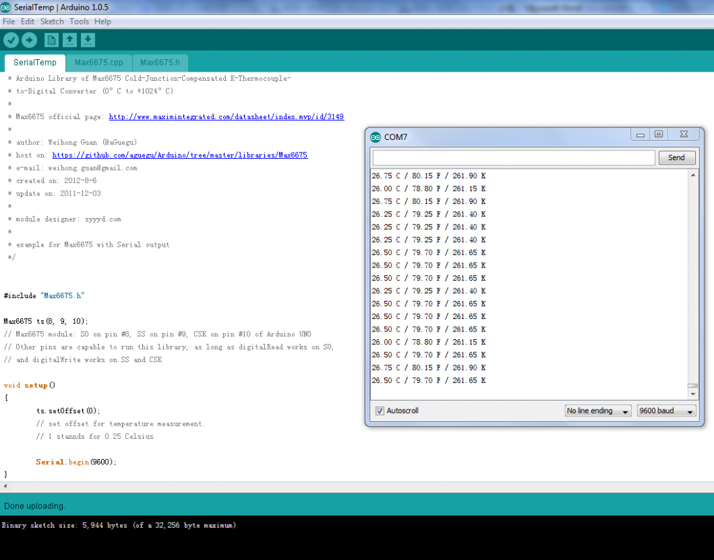
他家直接提供的代码包有问题,其中对应的Arduino程序无法打开。不知道是否有其他朋友也遇到过同样的问题。好在网上搜索到了对应的库 http://www.geek-workshop.com/forum.php?mod=viewthread&tid=4554&highlight=max6675 。测试了一下工作正常。最后代码如下

#include "Max6675.h"

Max6675 ts(8, 9, 10);
// Max6675 module: SO on pin #8, SS on pin #9, CSK on pin #10 of Arduino UNO
// Other pins are capable to run this library, as long as digitalRead works on SO,
// and digitalWrite works on SS and CSK

void setup()
{
	ts.setOffset(0);
	// set offset for temperature measurement.
	// 1 stannds for 0.25 Celsius

	Serial.begin(9600);
}


void loop()
{
	Serial.print(ts.getCelsius(), 2);
	Serial.print(" C / ");
	Serial.print(ts.getFahrenheit(), 2);
	Serial.print(" F / ");
	Serial.print(ts.getKelvin(), 2);
	Serial.print(" K\n");
	delay(300);
}

运行结果

完整的代码库下载

Max6675

PT100

Step to UEFI (20) —– 再论“ CLib 获得 ImageHandle”的问题

在翻看之前写的 《Step to UEFI (16) —– CLIB下获得 SystemTable》 【参考1】的时候偶然注意到:

加入头文件 #include Library/UefiBootServicesTableLib.h ,这个头文件的内容是

#ifndef __UEFI_BOOT_SERVICES_TABLE_LIB_H__
#define __UEFI_BOOT_SERVICES_TABLE_LIB_H__

///
/// Cache the Image Handle
///
extern EFI_HANDLE gImageHandle;

///
/// Cache pointer to the EFI System Table
///
extern EFI_SYSTEM_TABLE *gST;

///
/// Cache pointer to the EFI Boot Services Table
///
extern EFI_BOOT_SERVICES *gBS;

#endif

除了之前关注到的各种Table,居然还有一个 gImageHandle !!!

马上动手写了一个程序验证:

#include  <Uefi.h>
#include  <Library/UefiLib.h>
#include  <Library/ShellCEntryLib.h>

#include  <stdio.h>
#include  <stdlib.h>
#include <wchar.h>

extern EFI_BOOT_SERVICES             *gBS;
extern EFI_SYSTEM_TABLE				 *gST;
extern EFI_RUNTIME_SERVICES 		 *gRT;
extern EFI_HANDLE        			  gImageHandle;

//SimpleTextInputEx.harderr
//#define	EFI_SHIFT_STATE_VALID		0x80000000
//#define EFI_LEFT_CONTROL_PRESSED	0x00000002

EFI_STATUS
EFIAPI
NotificationFunction(
	IN EFI_KEY_DATA	*KeyData
)
{
	printf("This is a test from www.lab-z.com \n");		
	return(EFI_SUCCESS);
}

/***
  Demonstrates basic workings of the main() function by displaying a
  welcoming message.

  Note that the UEFI command line is composed of 16-bit UCS2 wide characters.
  The easiest way to access the command line parameters is to cast Argv as:
      wchar_t **wArgv = (wchar_t **)Argv;

  @retval  0         The application exited normally.
  @retval  Other     An error occurred.
***/
int
EFIAPI
main (
  IN int Argc,
  IN char **Argv
  )
{
	EFI_SIMPLE_TEXT_INPUT_EX_PROTOCOL *SimpleEx;
	EFI_KEY_DATA	KeyData;
	EFI_STATUS		Status;
	EFI_HANDLE		CtrlCNotifyHandle = NULL;
	INTN			i;

 	Status = gBS -> OpenProtocol(
		gST -> ConsoleInHandle,
		&gEfiSimpleTextInputExProtocolGuid,
		(VOID**)&SimpleEx,
		gImageHandle,
		NULL,
		EFI_OPEN_PROTOCOL_GET_PROTOCOL);

	if (EFI_ERROR(Status)) {
		printf("OpenProtocol ERROR!!\n");
	}		

	KeyData.KeyState.KeyToggleState = 0;
	KeyData.Key.ScanCode			= 0;
	KeyData.KeyState.KeyShiftState 	= EFI_SHIFT_STATE_VALID | EFI_LEFT_CONTROL_PRESSED;
	KeyData.Key.UnicodeChar			= L's';

	Status = SimpleEx -> RegisterKeyNotify (
			SimpleEx,
			&KeyData,
			NotificationFunction,
			&CtrlCNotifyHandle);

	for (i=0;i<200;i++)
	 {
		printf("Test\n");		
		gBS -> Stall (5000);
      }

	Status = SimpleEx -> UnregisterKeyNotify(SimpleEx, CtrlCNotifyHandle);

  return EFI_SUCCESS;
}

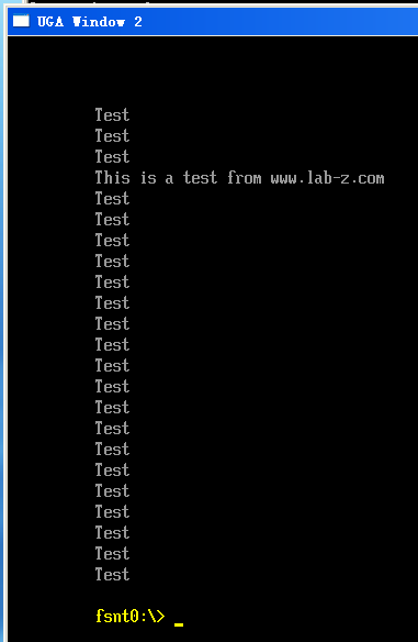
运行结果和之前文章一样,就是说这个方法是OK的!

mainh2


程序下载 Mainh2

==============================================================================

这样的话,之前提到的方法完全就是“脱了裤子放屁—-多此一举”。

另外,再说点好玩的事情,前几天朋友圈里有人转了一篇文章,吹嘘他的“重要”发明“竖版世界地图”。文章的观点基本上是:中国最大的敌人是美国。美国和中国有多远?正常人看普通的世界地图会被误导,以为要横跨太平洋。但是实际上中国和美国如果从北极的方向走才是最近的。结论:看普通的世界地图会导致如此不堪的错误,用我发明的竖版世界地图就万事大吉。文章还在暗示设计北斗导航系统,差点因为看普通的地图而导致大错。

这里放一个“竖版的世界地图”【来自红网,Baidu搜出来的结果】

U9383P704DT20140623085032

怎么说呢,看着是挺别扭的,地球仿佛将菊花对准了你…………

我想看国家疆域,你把一个水球给我干嘛?

上小学和初中时学过一点地理知识。对于地图来说,基本上就是准确的看着不舒服,舒服看着不准确(投影决定的),根本原因是地球不是立方体,再仔细追究丫也不是标准的球体。

又想起来看过一篇文章,经常出国的人看每个国家的地图都觉得很别扭“为毛中国不是在中间?”

除了习惯的力量,还有这种竖版的地图,上面是北还是南?另外,莫非搞卫星的人不知道世界上还有一种“用空间中到定点的距离小于或等于定长的所有点组成图形的结构”结合“通用标记地面地理特性的方法”贴图在一起的通常我们称之为“地球仪”的东西吗?

说到这里,我也想有一个“伟大”的发明,那就是按照地球表面的凸凹形状做一个地球仪—-已经有了?没关系,那我就按照表面G的不同绘制吧。我也编一个故事:NK发射火箭没人考虑G点差别,一直无法满意。后来偶尔最高统帅看到我的地球仪,茅塞顿开………现在我的地球仪对NK是禁运的………

建议将 Google Earth 禁掉,我相信我的发明能更加“伟大”。

参考:

1.http://www.lab-z.com/step-to-uefi-16%EF%BC%89-clib%E4%B8%8B%E8%8E%B7%E5%BE%97-systemtable/ Step to UEFI (16) —– CLIB下获得 SystemTable

USB 控制七段数码管(II)

换个免驱的方式。前面之所以能免驱动,是因为我走的是USB HID协议。除了这个,更常见的是USB Mass Storage协议,就是我们常见的U盘走的协议。对于这个协议在《圈圈教你玩USB》中有详细介绍。下面就讲一下如何把我这个设备移植到MSD协议上。

首先说一下Firmware设计上的改变。

驱动数码管同样使用之前HID中的那种,用一个Timer不断循环点亮每一个数码管。因此,在Main.c中加入Timer0的初始化和中断服务程序。它会按照zBuf中给出来的依次点亮四个数码管。

volatile uint8 zBuf[]={1,2,3,4}; //用来保存8字节的输出报告。

/********************************************************************
函数功能:定时器0初始化,用来做键盘扫描。
入口参数:无。
返    回:无。
备    注:无。
********************************************************************/
void InitTimer0(void)
{
 TMOD&=0xF0;
 TMOD|=0x01;
 ET0=1;
 TR0=1;
}

/********************************************************************
函数功能:定时器0中断处理。
入口参数:无。
返    回:无。
备    注:22.1184M晶体约5ms中断一次。
********************************************************************/
void Timer0Isr(void) interrupt 1
{ 
   static i=0; 

//定时器0重装,定时间隔为5ms,加15是为了修正重装所花费时间
//这个值可以通过软件仿真来确定,在这里设置断点,调整使两次运行
//时间差刚好为5ms即可。
 TH0=(65536-Fclk/1000/12*5+15)/256;	 
 TL0=(65536-Fclk/1000/12*5+15)%256;   // 

	P2=1 << i;
	P1=zBuf[i];
	i++;
	if (i==4) {i=0;}
}
/*******************************************************************/


PC对USB Mass Storage 设备传数据,使用的是 WRITE(10) 命令,具体的数据会在批量传输协议中的批量数据阶段传输给设备。具体对应在代码中 SCSI.C 中的 procScsiOutData 中,我们在这里将收到的输局赋值给 zBuf.

/********************************************************************
函数功能:处理输出数据。
入口参数:无。
返    回:无。
备    注:无。
********************************************************************/
void ProcScsiOutData(void)
{
 uint8 Len;
 int i;

 //读端点2数据
 Len=D12ReadEndpointBuffer(4,EP2_SIZE,Ep2Buffer);

 //LabzDebug_Start 
 zBuf[0]=Ep2Buffer[0]; zBuf[1]=Ep2Buffer[1]; zBuf[2]=Ep2Buffer[2]; zBuf[3]=Ep2Buffer[3];

  PrintHex(zBuf[0]);
  PrintHex(zBuf[1]);
  PrintHex(zBuf[2]);
  PrintHex(zBuf[3]);
  Prints("\r\n");

 #ifdef DEBUG1
 Prints("收到 \r\n");
 for ( i=0; i <4;i++)
 {
  PrintHex(*(Ep2Buffer+i));  //如果需要显示调试信息,则显示发送的数据
  if(((i+1)%16)==0)Prints("\r\n"); //每16字节换行一次
  PrintHex(zBuf[0]);
  PrintHex(zBuf[1]);
  PrintHex(zBuf[2]);
  PrintHex(zBuf[3]);
  if((Len%16)!=0)Prints("\r\n"); //换行
 }
 #endif
 //LabZDebug_End
 Ep2DataLength-=Len;
 //清除端点缓冲区
 D12ClearBuffer();
 //由于没有存储器,这里将缓冲区清0模拟数据处理
 while(Len)
 {
  Ep2Buffer[Len]=0; //缓冲区清0
  Len--;
 }
 
 //数据传输完毕,进入到状态阶段
 if(Ep2DataLength==0)
 {
  //此时Ep2DataLength为0,并且处于数据阶段,调用发送数据函数将返回CSW
  Ep2SendData();
 }
}


只要做这一点Change,Firmware即可支持。

其次说一下上位机程序的设计。

因为模拟成一个U盘,因此,按照访问硬盘的方式即可传输数据。先是使用CreateFile打开PhysicalDriverX (特别注意:从PhysicalDriver0开始),之后就用 WriteFile 进行写入,特别注意,写入的最小单位是512字节,不能小于这个值。最后CloseHandle关闭即可。

最初,程序设计出来是这样的

CreateFile(PhysicalDrive3)

while Keypressed=false
{
WriteFile (512 Byte)
}

CloseHandle

结果发现非常奇怪,只有第一次能够顺利写入512Bytes,之后会不断出现 Error 5 ERROR_ACCESS_DENIED 5 (0x5) Access is denied. 的问题。为了防止是我设备不稳定造成的,我还用一个U盘进行试验(特别注意,操作会导致U盘内容不可读!!!)在Windows 7 x64和WindowsXP 32 都有同样的现象。请教天杀,他回复“想起来了,Win7的确有这个问题,可以写分区表,但是不能写后续的分区位置,是会被拒绝的。要写数据必须通过分区去写,或者将分区删除。你可以把设备识别成USB HDD,然后没有分区,这样应该可以全盘去写。如果是没有分区的那种U盘形式,是可能会被禁止写入的。”

这样的话,第一个方案就出来了,每次都要用CreateFile打开硬盘,写入之后再Close。

#include "stdafx.h"
#include <windows.h>
#include <stdio.h>
#include <stdlib.h>
#include <conio.h>
#include <time.h>

int main(int argc, char *argv[])
{
   HANDLE hFile;
   BOOL fSuccess;
   char txchar[512];
   DWORD iBytesWritten;
   byte Seven_Dig[10]={   0x40,  // = 0
						  0x79,  // = 1	
						  0x24,  // = 2
						  0x30,  // = 3
                          0x19,  // = 4	
						  0x12,  // = 5
						  0x02,  // = 6
                          0x78,  // = 7	
						  0x00,  // = 8
						  0x10,  // = 9
                             }; 


 int n=1234;	
 while (kbhit()==0)
  {
	  hFile = CreateFile(L"\\\\.\\PhysicalDrive2",
                    GENERIC_WRITE,
                    FILE_SHARE_WRITE,    // must be opened with exclusive-access
                    NULL, // no security attributes
                    OPEN_EXISTING, // must use OPEN_EXISTING
                    0,    // not overlapped I/O
                    NULL  // hTemplate must be NULL for comm devices
                    );

   if (hFile == INVALID_HANDLE_VALUE) 
   {
       // Handle the error.
        printf ("CreateFile failed with error %d.\n", GetLastError());
		system("PAUSE");
        return (1);
   }

   txchar[0]=Seven_Dig[n / 1000 % 10];
   txchar[1]=Seven_Dig[n / 100 % 10];
   txchar[2]=Seven_Dig[n / 10 % 10];
   txchar[3]=Seven_Dig[n %10];
								
  for (int i=1;i<512 /4;i++) 
   {
 txchar[i*4]=txchar[0];
 txchar[i*4+1]=txchar[1];
  txchar[i*4+2]=txchar[2];
  txchar[i*4+3]=txchar[3];
   }

fSuccess=WriteFile(hFile, &txchar, 512, &iBytesWritten,NULL);
printf ("done send %d bytes.Status [%d] \n", iBytesWritten,fSuccess);
printf ("Get lasterror %d\n", GetLastError());
printf("%d \n",n);

n=(n++)%10000;
FlushFileBuffers(hFile);
Sleep(1000);
 CloseHandle(hFile);
}//while (kbhit()==0)

   system("PAUSE");


   return (0);
}


第二个方案就是每次用WriteFile写入之后,我们再重置指针,再从最开始写入。类似下面的方案。

CreateFile(PhysicalDrive3)

while Keypressed=false
{
SetFilePointer(hFile,0,0,FILE_BEGIN);
WriteFile (512 Byte)
}

CloseHandle

实际的效果和之前的HID的方式相同。

Firmware下载 USB7SegFW

第一种上位机程序下载
exp1

第二种上位机程序下载
exp2

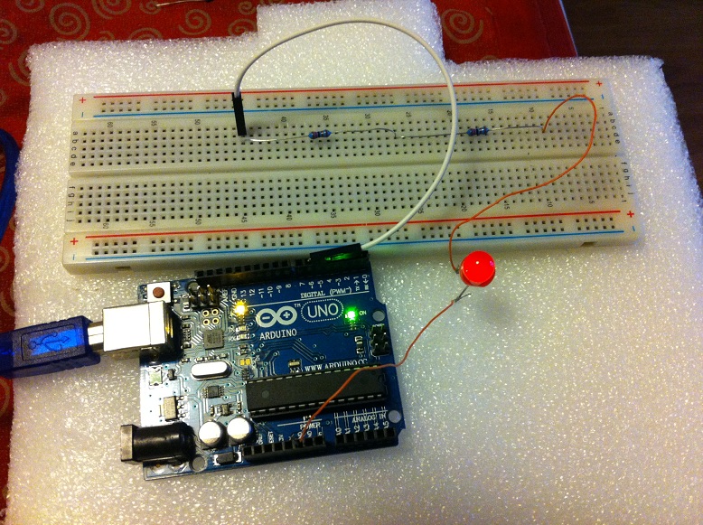
PWM 控制LED亮度

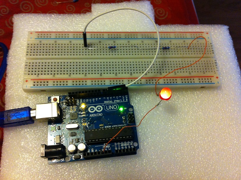
写了一个简单的程序,使用Arduino Uno上 PWN Pin 来控制一个LED的亮度。

代码方面是从串口接收信息,“[”减小,“]”增加

int  n=100;
void setup()
{
    Serial.begin(9600);
    pinMode(6,OUTPUT);      //该端口需要选择有#号标识的数字口
}

void loop()
{
  char  c;

    while (Serial.available() > 0)  
    {
        c=Serial.read();
        if (']'==c) 
          {
            n=n+5;
          }
        if ('['==c) 
          {
            n=n-5;
          }
       if (n>255) {n=0;}
       if (n<0) {n=255;}   
       analogWrite(6,n); 
       Serial.println(n);

    }
}

电路连接仿照【参考1】.刚开始使用220欧的电阻,发现亮度变化不均匀,在100以上之后看不出来亮度有多少变化,之后,改成 2.4K  电阻(2个1.2K串联),表现更好。

PWMLED1 PWMLED2


参考:

1.http://www.geek-workshop.com/forum.php?mod=viewthread&tid=1054&highlight=pwm Arduino入门教程–第五课–按钮PWM控制LED亮度

Step to UEFI (19) —– Shell Command Stall 命令的分析

随手翻了一下 UEFI Shell 的 Source ,看了一下 Stall 命令觉得挺有意思,研究了一下。

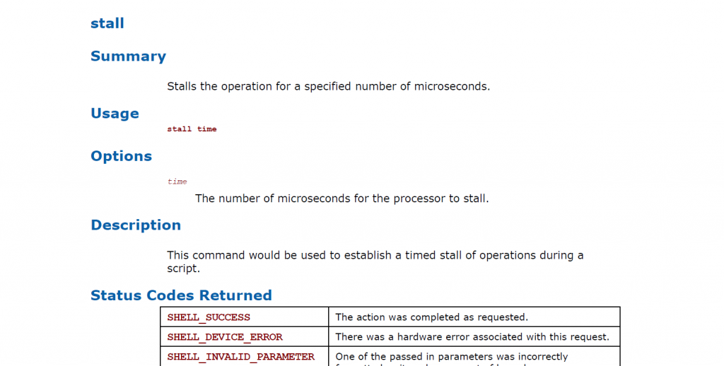
这个命令的介绍如下,实现了一个很简单的功能:暂停 xxx 微妙 (MicroSeconds 百万分之一秒)

stallcmd

对应的代码在 \Shell\stall\stall.c 可以看到

关键部分的代码是:

  Microseconds = Atoi (ChkPck.VarList->VarStr);  //要暂停的时间 UINTN Microseconds;
  PrintToken (STRING_TOKEN (STR_STALL_FOR), HiiStallHandle, Microseconds);
  Remaining = Microseconds % 100000;
  Status    = RT->GetTime (&TmpTime, NULL);      //取当前时间 
  if (EFI_ERROR (Status)) {
    Status = EFI_ABORTED;
    goto Done;
  }

  MilliSeconds1 = (TmpTime.Hour * 3600 + TmpTime.Minute * 60 + TmpTime.Second) * 1000; //当前时间转化为毫秒
  while (Microseconds - Remaining) {
    //
    // Break the execution?
    //
    if (GetExecutionBreak ()) {  //允许打断
      goto Done;
    }

    BS->Stall (100000);          //暂停 1秒
    Status = RT->GetTime (&TmpTime, NULL);
    if (EFI_ERROR (Status)) {
      Status = EFI_ABORTED;
      goto Done;
    }

    MilliSeconds2 = (TmpTime.Hour * 3600 + TmpTime.Minute * 60 + TmpTime.Second) * 1000;
    if (MilliSeconds2 < MilliSeconds1) { //如果发生跨天的情况,算了一下 0xFFFFFFFF 个微秒最多只能跨一天
      MilliSeconds2 += (24 * 3600 * 1000);
    }

    if ((Microseconds - Remaining) / 1000 <= (MilliSeconds2 - MilliSeconds1)) {
      break;
    }
  } // while (Microseconds - Remaining) 结束

  BS->Stall (Remaining);


看起来整个过程就是:使用 BS 的 Stall 不断做短时间的暂停,直到完成预订的Stall 时间。不过想不太明白,这样做同直接 BS -> Stall 指定的时间相比能获得什么好处?莫非是给一个能够用 Ctrl-Break 的机会么?

参考:
1. Shell Stall 命令的介绍,来自 UEFI Shell Specification Rev 2.1
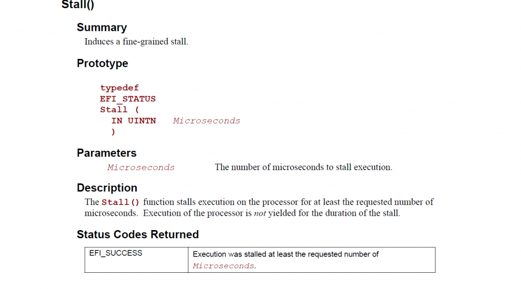
2. BS->Stall 的介绍,来自 UEFI Spec 2.4
bsstall

通过WriteFile对硬盘发送数据

下面这个程序首先用 CreateFile 打开 PhysicalDiskX 然后使用 CreateFile 向里面写入数据。

#include "stdafx.h"
#include <windows.h>
#include <stdio.h>
#include <conio.h>

int main(int argc, char *argv[])
{
   HANDLE hFile;
   BOOL fSuccess;
   char txchar[512];
   DWORD iBytesWritten;

   hFile = CreateFile(L"\\\\.\\PhysicalDrive1",
                    GENERIC_WRITE,
                    FILE_SHARE_WRITE,    // must be opened with exclusive-access
                    NULL, // no security attributes
                    OPEN_EXISTING, // must use OPEN_EXISTING
                    0,    // not overlapped I/O
                    NULL  // hTemplate must be NULL for comm devices
                    );

   if (hFile == INVALID_HANDLE_VALUE) 
   {
       // Handle the error.
        printf ("CreateFile failed with error %d.\n", GetLastError());
		system("PAUSE");
        return (1);
   }

   txchar[0]='l'; txchar[1]='a';txchar[2]='b';txchar[3]='z';

   //有资料说用这个函数对磁盘写的最小值是 512 bytes 我实验了一下如果小于此会出现error
   fSuccess=WriteFile(hFile, &txchar, 512, &iBytesWritten,NULL);
   printf ("done send %d bytes.Status [%d] \n", iBytesWritten,fSuccess,iBytesWritten);
   printf ("Get lasterror %d\n", GetLastError());

   system("PAUSE");
   CloseHandle(hFile);

   return (0);
}


我的实验是在虚拟机中进行的。特别提醒:本次实验可能会损害你的数据,请务必小心。如果系统有安装杀毒软件,有可能被判定为病毒行为。实验的目标盘是一个U盘,盘符为 G:

a

之后,先用 Winhex 打开,我们可以看到开始的几个字符是 abcd

b

运行我们的程序(可以看到发送 512 Bytes Status=1 表示 Success GetLastError=0 表示无错误)
c

我们需要重新打开一次硬盘(WinHex有磁盘修改感知功能,但是在这里不好用)
e

我们可以看到最开始的几个字符被修改了,这说明我们的程序是由效果的的。
d

完整的程序下载:

sendbywritefile

参考:

1.http://msdn.microsoft.com/en-us/library/windows/desktop/aa365747(v=vs.85).aspx MSDN WriteFile function

2.http://msdn.microsoft.com/en-us/library/windows/desktop/ms681382(v=vs.85).aspx MSDN System Error 对于确定 GetLastError 返回值很有用

3.http://msdn.microsoft.com/en-us/library/windows/desktop/aa363858(v=vs.85).aspx MSDN CreateFile function