使用 CH567 制作一个USB 键盘

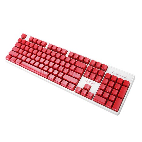
这一次使用 CH567 制作一个USB键盘,参考的对象是Dostyle 的MK60 机械键盘。

Dostyle MK60 机械键盘

同样的,使用 USBlyzer 抓取描述符信息:

USB Composite Device

Connection StatusDevice connected
Current Configuration1
SpeedFull (12 Mbit/s)
Device Address8
Number Of Open Pipes2

Device Descriptor Gaming KB

OffsetFieldSizeValueDescription
0bLength112h
1bDescriptorType101hDevice
2bcdUSB20110hUSB Spec 1.1
4bDeviceClass100hClass info in Ifc Descriptors
5bDeviceSubClass100h
6bDeviceProtocol100h
7bMaxPacketSize0108h8 bytes
8idVendor2258Ah
10idProduct2002Ah
12bcdDevice21201h12.01
14iManufacturer101h“SINO WEALTH”
15iProduct102h“Gaming KB “
16iSerialNumber100h
17bNumConfigurations101h

Configuration Descriptor 1 Bus Powered, 500 mA

OffsetFieldSizeValueDescription
0bLength109h
1bDescriptorType102hConfiguration
2wTotalLength2003Bh
4bNumInterfaces102h
5bConfigurationValue101h
6iConfiguration100h
7bmAttributes1A0hBus Powered, Remote Wakeup
4..0: Reserved…00000 
5: Remote Wakeup..1….. Yes
6: Self Powered.0…… No, Bus Powered
7: Reserved (set to one)
(bus-powered for 1.0)
1……. 
8bMaxPower1FAh500 mA

Interface Descriptor 0/0 HID, 1 Endpoint

OffsetFieldSizeValueDescription
0bLength109h
1bDescriptorType104hInterface
2bInterfaceNumber100h
3bAlternateSetting100h
4bNumEndpoints101h
5bInterfaceClass103hHID
6bInterfaceSubClass101hBoot Interface
7bInterfaceProtocol101hKeyboard
8iInterface100h

HID Descriptor

OffsetFieldSizeValueDescription
0bLength109h
1bDescriptorType121hHID
2bcdHID20111h1.11
4bCountryCode100h
5bNumDescriptors101h
6bDescriptorType122hReport
7wDescriptorLength20043h67 bytes

Endpoint Descriptor 81 1 In, Interrupt, 1 ms

OffsetFieldSizeValueDescription
0bLength107h
1bDescriptorType105hEndpoint
2bEndpointAddress181h1 In
3bmAttributes103hInterrupt
1..0: Transfer Type……11 Interrupt
7..2: Reserved000000.. 
4wMaxPacketSize20008h8 bytes
6bInterval101h1 ms

Interface Descriptor 1/0 HID, 1 Endpoint

OffsetFieldSizeValueDescription
0bLength109h
1bDescriptorType104hInterface
2bInterfaceNumber101h
3bAlternateSetting100h
4bNumEndpoints101h
5bInterfaceClass103hHID
6bInterfaceSubClass100h
7bInterfaceProtocol100h
8iInterface100h

HID Descriptor

OffsetFieldSizeValueDescription
0bLength109h
1bDescriptorType121hHID
2bcdHID20111h1.11
4bCountryCode100h
5bNumDescriptors101h
6bDescriptorType122hReport
7wDescriptorLength200CCh204 bytes

Endpoint Descriptor 82 2 In, Interrupt, 1 ms

OffsetFieldSizeValueDescription
0bLength107h
1bDescriptorType105hEndpoint
2bEndpointAddress182h2 In
3bmAttributes103hInterrupt
1..0: Transfer Type……11 Interrupt
7..2: Reserved000000.. 
4wMaxPacketSize20010h16 bytes
6bInterval101h1 ms

Interface 0 HID Report Descriptor Keyboard

Item Tag (Value)Raw Data
Usage Page (Generic Desktop)05 01 
Usage (Keyboard)09 06 
Collection (Application)A1 01 
    Usage Page (Keyboard/Keypad)05 07 
    Usage Minimum (Keyboard Left Control)19 E0 
    Usage Maximum (Keyboard Right GUI)29 E7 
    Logical Minimum (0)15 00 
    Logical Maximum (1)25 01 
    Report Count (8)95 08 
    Report Size (1)75 01 
    Input (Data,Var,Abs,NWrp,Lin,Pref,NNul,Bit)81 02 
    Report Count (1)95 01 
    Report Size (8)75 08 
    Input (Cnst,Var,Abs,NWrp,Lin,Pref,NNul,Bit)81 03 
    Report Count (6)95 06 
    Report Size (8)75 08 
    Logical Minimum (0)15 00 
    Logical Maximum (255)26 FF 00 
    Usage Page (Keyboard/Keypad)05 07 
    Usage Minimum (Undefined)19 00 
    Usage Maximum2A FF 00 
    Input (Data,Ary,Abs)81 00 
    Logical Maximum (1)25 01 
    Report Count (5)95 05 
    Report Size (1)75 01 
    Usage Page (LEDs)05 08 
    Usage Minimum (Num Lock)19 01 
    Usage Maximum (Kana)29 05 
    Output (Data,Var,Abs,NWrp,Lin,Pref,NNul,NVol,Bit)91 02 
    Report Count (1)95 01 
    Report Size (3)75 03 
    Output (Cnst,Var,Abs,NWrp,Lin,Pref,NNul,NVol,Bit)91 03 
End CollectionC0 

Interface 1 HID Report Descriptor System Control

Item Tag (Value)Raw Data
Usage Page (Generic Desktop)05 01 
Usage (System Control)09 80 
Collection (Application)A1 01 
    Report ID (1)85 01 
    Usage Minimum (System Power Down)19 81 
    Usage Maximum (System Wake Up)29 83 
    Logical Minimum (0)15 00 
    Logical Maximum (1)25 01 
    Report Size (1)75 01 
    Report Count (3)95 03 
    Input (Data,Var,Abs,NWrp,Lin,Pref,NNul,Bit)81 02 
    Report Count (5)95 05 
    Input (Cnst,Ary,Abs)81 01 
End CollectionC0 
Usage Page (Consumer Devices)05 0C 
Usage (Consumer Control)09 01 
Collection (Application)A1 01 
    Report ID (2)85 02 
    Usage Minimum (Undefined)19 00 
    Usage Maximum (AC Format)2A 3C 02 
    Logical Minimum (0)15 00 
    Logical Maximum (572)26 3C 02 
    Report Count (1)95 01 
    Report Size (16)75 10 
    Input (Data,Ary,Abs)81 00 
End CollectionC0 
Usage Page (Vendor-Defined 1)06 00 FF 
Usage (Vendor-Defined 1)09 01 
Collection (Application)A1 01 
    Report ID (5)85 05 
    Logical Minimum (0)15 00 
    Logical Maximum (255)26 FF 00 
    Usage Minimum (Vendor-Defined 1)19 01 
    Usage Maximum (Vendor-Defined 2)29 02 
    Report Size (8)75 08 
    Report Count (5)95 05 
    Feature (Data,Var,Abs,NWrp,Lin,Pref,NNul,NVol,Bit)B1 02 
End CollectionC0 
Usage Page (Generic Desktop)05 01 
Usage (Keyboard)09 06 
Collection (Application)A1 01 
    Report ID (6)85 06 
    Logical Minimum (0)15 00 
    Logical Maximum (1)25 01 
    Report Size (1)75 01 
    Report Count (112)95 70 
    Usage Page (Keyboard/Keypad)05 07 
    Usage Minimum (Keyboard Left Control)19 E0 
    Usage Maximum (Keyboard Right GUI)29 E7 
    Usage Minimum (Undefined)19 00 
    Usage Maximum (Keypad =)29 67 
    Input (Data,Var,Abs,NWrp,Lin,Pref,NNul,Bit)81 02 
    Report Count (8)95 08 
    Input (Cnst,Ary,Abs)81 01 
End CollectionC0 
Usage Page (Vendor-Defined 1)06 00 FF 
Usage (Vendor-Defined 1)09 01 
Collection (Application)A1 01 
    Report ID (9)85 09 
    Logical Minimum (0)15 00 
    Logical Maximum (255)26 FF 00 
    Usage (Undefined)09 00 
    Report Size (8)75 08 
    Report Count (504)96 F8 01 
    Feature (Data,Var,Abs,NWrp,Lin,Pref,NNul,NVol,Bit)B1 02 
End CollectionC0 
Usage Page (Vendor-Defined 1)06 00 FF 
Usage (Vendor-Defined 1)09 01 
Collection (Application)A1 01 
    Report ID (10)85 0A 
    Logical Minimum (0)15 00 
    Logical Maximum (255)26 FF 00 
    Usage (Undefined)09 00 
    Report Size (8)75 08 
    Report Count (41)95 29 
    Feature (Data,Var,Abs,NWrp,Lin,Pref,NNul,NVol,Bit)B1 02 
End CollectionC0 
Usage Page (Vendor-Defined 1)06 00 FF 
Usage (Vendor-Defined 1)09 01 
Collection (Application)A1 01 
    Report ID (11)85 0B 
    Logical Minimum (0)15 00 
    Logical Maximum (255)26 FF 00 
    Usage (Undefined)09 00 
    Report Size (8)75 08 
    Report Count (126)95 7E 
    Feature (Data,Var,Abs,NWrp,Lin,Pref,NNul,NVol,Bit)B1 02 
End CollectionC0 
Usage Page (Vendor-Defined 1)06 00 FF 
Usage (Vendor-Defined 1)09 01 
Collection (Application)A1 01 
    Report ID (12)85 0C 
    Logical Minimum (0)15 00 
    Logical Maximum (255)26 FF 00 
    Usage (Undefined)09 00 
    Report Size (8)75 08 
    Report Count (1920)96 80 07 
    Feature (Data,Var,Abs,NWrp,Lin,Pref,NNul,NVol,Bit)B1 02 
End CollectionC0 

This report was generated by USBlyzer

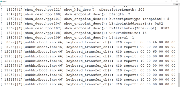
需要特别注意的是:这个设备是 USB Full Speed(12Mbits/s)的,必须在文件头部设置为 Full Speed,如果继续使用 Low Speed,插入之后读取描述符后 Host就会停止继续发送数据(Windows 行为,我不知道原因)。

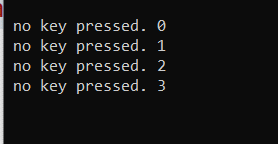
除此之外,和之前的鼠标代码相比还增加了一个HID 描述符,另外,在 Main 中定时发送打开Windows 菜单(Win按键)。

USB Host Shield 通过USB Hub 连接多个键盘

USB Host Shield 本身是支持USB Hub的,这样我们可以方便的一次性连接多个USB 设备。这次以USB 键盘为例进行测试。

USB Hub 的使用还是比较简单的,连接好之后,建议运行 USB_Host_Shield_Library_2.0\examples\hub_demo 这个示例代码进行测试,它会枚举当前USB Hub上的所有 USB 设备的描述符信息,通过这样的方法我们可以知道硬件是否能够工作正常。

前述代码测试通过后,我们就可以编写代码来获得按键信息了。

1. KBUnderHub.ino 代码中必须使用 USBHub ,之后,因为测试有3个键盘,所以要声明 kb1 到 kb3 三个设备

USB Usb;

USBHub Hub(&Usb);

KBSET kb1(&Usb);

KBSET kb2(&Usb);

KBSET kb3(&Usb);

2. KeyboardSets.h 代码中,申明一些我们需要的结构体如下:

// 当前支持的键盘数量
#define KBNUM 3

class KBSET : public HIDUniversal {
  public:
    KBSET(USB *p) : HIDUniversal(p) {};
    bool connected() {
      return HIDUniversal::isReady();
    };
    // 本次收到数据的键盘编号
    uint8_t  Current;
    // 存放第x个键盘是否有改变发生的标记
    bool     Changed[KBNUM];
    // 存放第x个键盘当前收到的缓冲区长度
    uint8_t  BufferSize[KBNUM];
    // 存放第x个键盘收到的缓冲区数据
    uint8_t  Buffer[KBNUM][64];
    // 存放第x个键盘的PID 和 VID
    uint16_t PID[KBNUM];
    uint16_t VID[KBNUM];
  private:
    void ParseHIDData(USBHID *hid, bool is_rpt_id, uint8_t len, uint8_t *buf); // Called by the HIDUniversal library
    uint8_t  BufferSizeOld[KBNUM];
    uint8_t  BufferOld[KBNUM][64];
    // 当前收到的键盘数据总数
    uint8_t  TotolKB;
    uint8_t OnInitSuccessful() { // Called by the HIDUniversal library on success
      KBSET::TotolKB = 0;
      for (uint8_t j = 0; j < KBNUM; j++) {
        for (uint8_t i = 0; i < 64; i++) {
          KBSET::BufferOld[j][i]=0xFF;
        }
      }
      return 0;
    };
};

3. KeyboardSets.cpp

#include "KeyboardSets.h"

void KBSET::ParseHIDData(USBHID *hid, bool is_rpt_id, uint8_t len, uint8_t *buf) {
  /*
    if (len && buf)  {
      Notify(PSTR("\r\n"), 0x80);
      for (uint8_t i = 0; i < len; i++) {
        D_PrintHex<uint8_t > (buf[i], 0x80);
        Notify(PSTR(" "), 0x80);
      }
    }
  */

  // 在 KBSET 中查找记录
  KBSET::Current = 0xFF;
  for (uint8_t i = 0; i < KBNUM; i++) {
    //
    if ((KBSET::PID[i] == HIDUniversal::PID) && (KBSET::VID[i] == HIDUniversal::VID)) {
      KBSET::Current = i;
    }
  }
  // 如果查找不到
  if (KBSET::Current == 0xFF) {
    KBSET::Current = KBSET::TotolKB;
    KBSET::PID[KBSET::Current] = HIDUniversal::PID;
    KBSET::VID[KBSET::Current] = HIDUniversal::VID;
    KBSET::BufferSize[KBSET::Current] = len;
    KBSET::TotolKB++;
  }

  // 检查本次数据和上次数据是否有差别
  if (memcmp(BufferOld[KBSET::Current], buf, len) == 0) {
    // 没有差别
    KBSET::Changed[KBSET::Current] = false;
  } else {
    memcpy(Buffer[KBSET::Current], buf, len);
    // 有差别
    KBSET::Changed[KBSET::Current] = true;
    memcpy(BufferOld[KBSET::Current], buf, len);
    Serial.print("VID:"); Serial.print(KBSET::VID[KBSET::Current],HEX);
    Serial.print(" PID:"); Serial.println(KBSET::PID[KBSET::Current],HEX);
    for (uint8_t i = 0; i < KBSET::BufferSize[KBSET::Current]; i++) {
      Serial.print((byte)(KBSET::Buffer[KBSET::Current][i]), HEX);
      Serial.print(" ");
    }
    Serial.println("");
  }
}

工作流程:当有按键事件发生时,库会调用 ParseHIDData() 这个函数,从设备获得的设备数据放在buf,产生数据的设备PID和 VID 在HIDUniversal::PID和HIDUniversal::VID中。之后,我们会在KBSET::PID VID数组中查找当前产生数据的设备是否已存在,如果没有话,将这个设备的PID和VID 加入数组中。之后再将改设备产生的数据存放到Buffer 中。之后,再判断新取得的数据和之前的BufferOld中保存的是否相同,如果相同就打印输出。

这样,我们就能分别获得三个设备产生的按键信息。

我是用了一个大键盘,一个小键盘和一个barcode scanner 作为测试设备,可以看到串口能够输出。

工作测试的视频:

https://www.bilibili.com/video/BV1nu411q7i7?share_source=copy_web

完整代码下载:

使用 MAX3421e 一个潜在的风险是:芯片本身价格高,比如前一段这个芯片价格炒到50以上,并且有假货。

手工分析一个 GPT 分区的U盘

最近在研究FAT32 格式,研究的目标是一个256MB容量的虚拟硬盘。

最开始发现资料和手上的结果多有出入无法对的上。经过两天的研究恍然大悟:对不上是因为这个硬盘在FAT前面还有分区信息,就是说对于一个硬盘来说要先读取分区的划分信息,比如第一个分区是FAT32,第二个分区是NTFS……..之后再根据不同的分区类型解析出文件内容。

目前主流分区有2种:一种是传统的 MBR;另外一种是比较新的 GPT。这次实验的硬盘是GPT 分区。

硬盘整体数据分布如下,解析是从左到右的顺序:

布局分布【参考1】

为了方便查看数据,使用 WinHex 这个磁盘工具。

1.使用WinHex进行查看,打开硬盘:

2.可以看到这个U盘上有“Start Sectors” 、“Partition 1(e:)”和“Partition gap”三块内容。对于OS来说 Partition 1 就是展现给用户的 e盘。

3.具体分析

3.1 Start Sectors 对应着LBA 0-33,使用WinHex 自带模板分析

分析结果如下:

这是一个保护性的“假MBR”,作用是防止不识别GPT分区的格式意外破坏分区。0x0-0x1FF偏移(在LBA0中):提供了一个 Partition 的数组, EDK2示例代码会检查这里确定是“假MBR”;0x200-0x258 偏移(在LBA1中):给出第一个分区信息表的入口(Partition Entry LBA),一般为2,意思是这个信息表入口在 LBA 2 上;0x400-0x4A0偏移(在 LBA2中):给出第一个分区的入口(Starting LBA),这里可以看到第一个分区从 LBA 2048(D)开始

3.2 选中第一个分区,可以看到它位于 0x100000处(也就是 LBA 2048 处)。同样的继续使用内置模板进行查看获得基本信息

从上面我们可以看到,从这个位置开始 Reserved 了6190(D)个扇区,因此可以知道第一个FAT在LBA:2048+6190=8238(D)。查看 LBA 8238 (D)这个位置 ,看到的就是 FAT 表。下图框出来的就是每一个文件项。第一个簇标记为 0xFFFFFFF8,第二个簇为0xFFFFFFFFF(0号FAT项为肮脏标志;1号FAT项是一个结束标志,通常簇号是从2开始就是这个原因)。其余的0xFFFFFF0F表示这个簇对应的是目录或者文件的结尾。之前我们的讨论都是以扇区为单位的,等到了研究文件时,通常需要以簇为单位,二者之间的换算关系是 Sector Per cluster 参数给出的。例如,这个值为4,就表示1个Cluster 由4个Sector 组成。

3.3 上面的概念不太容易理解,直接跳到数据区来进行查看。数据区的开始在:2048+6190+1001+1001=10240 扇区的位置:

可以隐约看到右侧ASCII字符就是我们FAT32分区上的根目录(下图是切换到D: 的示意图,注意物理硬盘和分区上的扇区不同,本文都是以物理硬盘的扇区号为准):

我们知道 EFI 目录下有 BOOT 目录,其中有 BOOTX64.EFI 这个文件。我们下面的目标就是获得这个文件的内容。首先,移动光标到前面的 EFI 目录字样处

从菜单上选择模板 :

查看目录信息 如下:

目录EFI 的数据在数据区起始扇区号+(簇号-2)*(扇区数/簇)

6号簇的绝对LBA就是 10240+(6-2)*4==10256扇区

上面可以看到 BOOT 这个目录,再使用模板解析BOOT目录的数据

可以看到 BOOT 目录的数据位于9号簇,对应的绝对扇区是10240+(9-2)*4==10268

再查看这个扇区

这里就能看到 BOOTX64.EFI 文件了,再用模板解析 BOOTX64.EFI 的数据:

最终查看10240+(10-2)*4==10272扇区,就是 BOOTX64.EFI 的内容

从 10272到10275 是10号簇,接下来需要到 FAT中查看,可以看到下面的位置指向了11号簇,就是说BOOTX64.EFI 文件并未完结,接下来的内容可以在11号簇所在扇区

参考:

  1. http://www.jinbuguo.com/storage/gpt.html  GPT 分区详解
  2. https://www.dgxue.com/huifu/luoji/windwos-huifu/fat32/
  3. https://blog.csdn.net/li_wen01/article/details/79929730

VS2015 给Console 程序加上图标的方法

默认情况下, Console 程序的图标是下面这种。这次介绍一下如何用其他的图标来替换之。


1.创建一个 Win32 Console 程序。在 Resource Files上点右键:

2.在弹出的菜单上选择 AddàResource…, 这样就为项目创建了一个 Resource文件

3.双击生成的 rc文件

4.跳转之后在文件上使用右键,选择 “Add Resources….”

5.选择 Icon,然后 Import

6.弹出的对话框上选择你需要的 icon文件

7.导入之后,在导入的图标上单击右键,选择 Properties….

8.改ID为IDC_MAINFRAME

生成的EXE 如下:

参考:

1. https://blog.csdn.net/weixin_30603633/article/details/96342177

Step to UEFI (248)安装一个自定义的 ACPI Table

UEFI Spec 介绍了一个 EFI_ACPI_TABLE_PROTOCOL,定义如下:

EFI_ACPI_TABLE_PROTOCOL

从介绍可以看出,我们能够使用这个 PROTOCOL 添加(Install)或者删除(Uninstall)一个 ACPI Table。

首先准备一个 ACPI Table, 这里顶一个一个叫做 LBZT 的 Table。

DefinitionBlock ("LABZT.AML", "LBZT", 2, "", "", 0x0)
{
 Name(BUF1, Buffer(){0x00,0x01,0x02,0x03,0x04,0x05})
 Name(BUF2, "www.lab-z.com")
}

DefinitionBlock语法定义如下【参考1】:

DefinitionBlock 语法定义

AMLFileName 是给编译器看的,用于指定输出的 AML 文件名;

TableSignature 是 ACPI Table 的名字(4字节)

ComplianceRevision, 2以及大于2是指定64位;1或者0指定32位(这里我不清楚具体差别,做了一个实验,比如定义:Name(BUF3, 0x1122334455),当ComplianceRevision为0时,编译之后结果发生截断,实际定义是Name(BUF3, 0x22334455);但是当ComplianceRevision为2时,编译结果和代码相同)。如果在处理较大的数值时,需要特别注意这里。

OEMID OEM自定义 ID

TableID  OEM自定义Table 名称(8Bytes)

OEMRevision OEM自定义数值

接下来我们首先自定义一个 ACPI Table 如下:

DefinitionBlock ("LABZ64.AML", "LABZ", 2, "", "", 0x0)
{
 Name(BUF1, Buffer(){0x00,0x01,0x02,0x03,0x04,0x05})
 Name(BUF2, "www.lab-z.com")
 Name(BUF3, 0x1122334455)
}

编译之:

iasl.exe 编译 ASL

得到的是一个二进制文件LABZ64.aml

查看生成的 AML 文件

使用工具转化为C的定义,我们就可以在代码中直接使用了。测试代码如下:

#include  <Uefi.h>
#include  <Library/UefiLib.h>
#include  <Library/ShellCEntryLib.h>
#include  <Library/UefiBootServicesTableLib.h>
#include  <Protocol/AcpiTable.h>

extern EFI_BOOT_SERVICES         *gBS;

EFI_GUID gEfiAcpiTableProtocolGuid ={ 
                0xFFE06BDD, 0x6107, 0x46A6, 
                { 0x7B, 0xB2, 0x5A, 0x9C, 0x7E, 0xC5, 0x27, 0x5C }};
                
/* Contents of file LABZ64.aml */
const long int LABZ64_aml_size = 85;
const unsigned char LABZ64_aml[85] = {
    0x4C, 0x41, 0x42, 0x5A, 0x55, 0x00, 0x00, 0x00, 0x02, 0x7A, 0x00, 0x00, 0x00, 0x00, 0x00, 0x00,
    0x00, 0x00, 0x00, 0x00, 0x00, 0x00, 0x00, 0x00, 0x00, 0x00, 0x00, 0x00, 0x49, 0x4E, 0x54, 0x4C,
    0x18, 0x10, 0x19, 0x20, 0x08, 0x42, 0x55, 0x46, 0x31, 0x11, 0x09, 0x0A, 0x06, 0x00, 0x01, 0x02,
    0x03, 0x04, 0x05, 0x08, 0x42, 0x55, 0x46, 0x32, 0x0D, 0x77, 0x77, 0x77, 0x2E, 0x6C, 0x61, 0x62,
    0x2D, 0x7A, 0x2E, 0x63, 0x6F, 0x6D, 0x00, 0x08, 0x42, 0x55, 0x46, 0x33, 0x0E, 0x55, 0x44, 0x33,
    0x22, 0x11, 0x00, 0x00, 0x00
};
                
int
EFIAPI
main (
  IN int Argc,
  IN char **Argv
  )
{
        EFI_STATUS              Status;
        EFI_ACPI_TABLE_PROTOCOL *AcpiTableProtocol;
        UINTN                   TableKey;
        
        Status = gBS->LocateProtocol(
                           &gEfiAcpiTableProtocolGuid, 
                           NULL,
                           (VOID **)&AcpiTableProtocol);
        if (EFI_ERROR(Status)) {
            Print(L"Cannot find ACPI_TABLE_PROTOCOL \r\n");
            return Status;
        }
        
        AcpiTableProtocol->InstallAcpiTable(
                                AcpiTableProtocol,
                                (VOID *)LABZ64_aml,
                                LABZ64_aml_size,
                                &TableKey);
        gBS->CloseProtocol ( 
                        AcpiTableProtocol,
                        &gEfiAcpiTableProtocolGuid,
                        gImageHandle,
                        NULL );
        return EFI_SUCCESS;
}

实体机上进行测试,运行 att.efi 之后可以使用 Acpiview 命令查看到如下:

--------------- LABZ Table --------------- 

Address  : 0x44B1D000
Length   : 85
  
00000000 : 4C 41 42 5A 55 00 00 00 - 02 7A 00 00 00 00 00 00   LABZU....z......
00000010 : 00 00 00 00 00 00 00 00 - 00 00 00 00 49 4E 54 4C   ............INTL
00000020 : 18 10 19 20 08 42 55 46 - 31 11 09 0A 06 00 01 02   ... .BUF1.......
00000030 : 03 04 05 08 42 55 46 32 - 0D 77 77 77 2E 6C 61 62   ....BUF2.www.lab
00000040 : 2D 7A 2E 63 6F 6D 00 08 - 42 55 46 33 0E 55 44 33   -z.com..BUF3.UD3
00000050 : 22 11 00 00 00                                      "....

Table Checksum : OK

ACPI Table Header                    :
  Signature                          : LABZ
  Length                             : 85
  Revision                           : 2
  Checksum                           : 0x7A
  Oem ID                             :       
  Oem Table ID                       :         
  Oem Revision                       : 0x0
  Creator ID                         : INTL
  Creator Revision                   : 0x20191018

Table Statistics:
	0 Error(s)
	0 Warning(s)

再进一步,启动到 Windows后用 RW 进行查看也可以看到 LABZ Table

这里是新加入的 ACPI Table

完整代码下载:

参考:

1. https://acpica.org/sites/acpica/files/asl_tutorial_v20190625.pdf

Step to UEFI (247)从 SecCoreStartupWithStack 到 Pei

书接上回,下面的语句输出了第一条 Debug Log,它位于 SecMain.c 中:

  DEBUG ((DEBUG_INFO,
    "SecCoreStartupWithStack(0x%x, 0x%x)\n",
    (UINT32)(UINTN)BootFv,
    (UINT32)(UINTN)TopOfCurrentStack
));

接下来就使用下面的语句跳转到SecStartupPhase2中:

//
// Initialize Debug Agent to support source level debug in SEC/PEI phases before memory ready.

//
InitializeDebugAgent (DEBUG_AGENT_INIT_PREMEM_SEC, &amp;amp;SecCoreData, SecStartupPhase2);

这个函数位于 \MdeModulePkg\Library\DebugAgentLibNull\DebugAgentLibNull.c,从代码上看到就是一个跳转而已:

/**
  Initialize debug agent.

  This function is used to set up debug environment to support source level debugging.
  If certain Debug Agent Library instance has to save some private data in the stack,
  this function must work on the mode that doesn't return to the caller, then
  the caller needs to wrap up all rest of logic after InitializeDebugAgent() into one
  function and pass it into InitializeDebugAgent(). InitializeDebugAgent() is
  responsible to invoke the passing-in function at the end of InitializeDebugAgent().

  If the parameter Function is not NULL, Debug Agent Library instance will invoke it by
  passing in the Context to be its parameter.

  If Function() is NULL, Debug Agent Library instance will return after setup debug
  environment.

  @param[in] InitFlag     Init flag is used to decide the initialize process.
  @param[in] Context      Context needed according to InitFlag; it was optional.
  @param[in] Function     Continue function called by debug agent library; it was
                          optional.

**/
VOID
EFIAPI
InitializeDebugAgent (
  IN UINT32                InitFlag,
  IN VOID                  *Context, OPTIONAL
  IN DEBUG_AGENT_CONTINUE  Function  OPTIONAL
  )
{
  if (Function != NULL) {
    Function (Context);
  }
}

继续在 SecMain.c中执行SecStartupPhase2() 函数,这个函数负责找到 PEI Core 的 Entry Point

/**
  Caller provided function to be invoked at the end of InitializeDebugAgent().

  Entry point to the C language phase of SEC. After the SEC assembly
  code has initialized some temporary memory and set up the stack,
  the control is transferred to this function.

  @param[in] Context    The first input parameter of InitializeDebugAgent().

**/
VOID
EFIAPI
SecStartupPhase2(
  IN VOID                     *Context
  )

其中的跳转代码如下:

  //
  // Transfer the control to the PEI core
  //
  (*PeiCoreEntryPoint) (SecCoreData, (EFI_PEI_PPI_DESCRIPTOR *)&amp;mPrivateDispatchTable);

其中 PeiCoreEntryPoint 类型是 EFI_PEI_CORE_ENTRY_POINT ,定义可以在 \mdepkg\include\pi\PiPeiCis.h 看到:

/**
  The entry point of PEI Foundation.

  This function is the entry point for the PEI Foundation, which
  allows the SEC phase to pass information about the stack,
  temporary RAM and the Boot Firmware Volume. In addition, it also
  allows the SEC phase to pass services and data forward for use
  during the PEI phase in the form of one or more PPIs. These PPI's
  will be installed and/or immediately signaled if they are
  notification type. There is no limit to the number of additional
  PPIs that can be passed from SEC into the PEI Foundation. As part
  of its initialization phase, the PEI Foundation will add these
  SEC-hosted PPIs to its PPI database such that both the PEI
  Foundation and any modules can leverage the associated service
  calls and/or code in these early PPIs.

  @param SecCoreData    Points to a data structure containing
                        information about the PEI core's
                        operating environment, such as the size
                        and location of temporary RAM, the stack
                        location and the BFV location.

  @param PpiList        Points to a list of one or more PPI
                        descriptors to be installed initially by
                        the PEI core. An empty PPI list consists
                        of a single descriptor with the end-tag
                        EFI_PEI_PPI_DESCRIPTOR_TERMINATE_LIST.
                        As part of its initialization phase, the
                        PEI Foundation will add these SEC-hosted
                        PPIs to its PPI database such that both
                        the PEI Foundation and any modules can
                        leverage the associated service calls
                        and/or code in these early PPIs.


**/
typedef
VOID
(EFIAPI *EFI_PEI_CORE_ENTRY_POINT)(
  IN CONST  EFI_SEC_PEI_HAND_OFF    *SecCoreData,
  IN CONST  EFI_PEI_PPI_DESCRIPTOR  *PpiList
);

接下来的跳转进入\MdePkg\Library\PeiCoreEntryPoint\PeiCoreEntryPoint.c 中的ModuleEntryPoint()

/**
  The entry point of PE/COFF Image for the PEI Core.

  This function is the entry point for the PEI Foundation, which allows the SEC phase
  to pass information about the stack, temporary RAM and the Boot Firmware Volume.
  In addition, it also allows the SEC phase to pass services and data forward for use
  during the PEI phase in the form of one or more PPIs.
  There is no limit to the number of additional PPIs that can be passed from SEC into
  the PEI Foundation. As part of its initialization phase, the PEI Foundation will add
  these SEC-hosted PPIs to its PPI database such that both the PEI Foundation and any
  modules can leverage the associated service calls and/or code in these early PPIs.
  This function is required to call ProcessModuleEntryPointList() with the Context
  parameter set to NULL.  ProcessModuleEntryPoint() is never expected to return.
  The PEI Core is responsible for calling ProcessLibraryConstructorList() as soon as
  the PEI Services Table and the file handle for the PEI Core itself have been established.
  If ProcessModuleEntryPointList() returns, then ASSERT() and halt the system.

  @param SecCoreData  Points to a data structure containing information about the
                      PEI core's operating environment, such as the size and
                      location of temporary RAM, the stack location and the BFV
                      location.

  @param PpiList      Points to a list of one or more PPI descriptors to be
                      installed initially by the PEI core. An empty PPI list
                      consists of a single descriptor with the end-tag
                      EFI_PEI_PPI_DESCRIPTOR_TERMINATE_LIST.
                      As part of its initialization phase, the PEI Foundation will
                      add these SEC-hosted PPIs to its PPI database, such that both
                      the PEI Foundation and any modules can leverage the associated
                      service calls and/or code in these early PPIs.

**/
VOID
EFIAPI
_ModuleEntryPoint(
  IN CONST  EFI_SEC_PEI_HAND_OFF    *SecCoreData,
  IN CONST  EFI_PEI_PPI_DESCRIPTOR  *PpiList
)
{
  ProcessModuleEntryPointList (SecCoreData, PpiList, NULL);

  //
  // Should never return
  //
  ASSERT(FALSE);
  CpuDeadLoop ();
}

函数中会调用一个构造函数:

\Build\OvmfX64\NOOPT_VS2015x86\X64\MdeModulePkg\Core\Pei\PeiMain\DEBUG\AutoGen.c
VOID
EFIAPI
ProcessModuleEntryPointList (
  IN CONST  EFI_SEC_PEI_HAND_OFF    *SecCoreData,
  IN CONST  EFI_PEI_PPI_DESCRIPTOR  *PpiList,
  IN VOID                           *Context
  )

{
  PeiCore (SecCoreData, PpiList, Context);
}

最终,跳入位于\MdeModulePkg\Core\Pei\PeiMain\PeiMain.c中的如下函数:

/**
  This routine is invoked by main entry of PeiMain module during transition
  from SEC to PEI. After switching stack in the PEI core, it will restart
  with the old core data.

  @param SecCoreDataPtr  Points to a data structure containing information about the PEI core's operating
                         environment, such as the size and location of temporary RAM, the stack location and
                         the BFV location.
  @param PpiList         Points to a list of one or more PPI descriptors to be installed initially by the PEI core.
                         An empty PPI list consists of a single descriptor with the end-tag
                         EFI_PEI_PPI_DESCRIPTOR_TERMINATE_LIST. As part of its initialization
                         phase, the PEI Foundation will add these SEC-hosted PPIs to its PPI database such
                         that both the PEI Foundation and any modules can leverage the associated service
                         calls and/or code in these early PPIs
  @param Data            Pointer to old core data that is used to initialize the
                         core's data areas.
                         If NULL, it is first PeiCore entering.

**/
VOID
EFIAPI
PeiCore (
  IN CONST EFI_SEC_PEI_HAND_OFF        *SecCoreDataPtr,
  IN CONST EFI_PEI_PPI_DESCRIPTOR      *PpiList,
  IN VOID                              *Data
  )

前面可以看到,这里是通过 ProcessModuleEntryPointList (SecCoreData, PpiList, NULL); 进行调用的,因此,这里Data==NULL,所以也是第一次运行:

  //
  // Retrieve context passed into PEI Core
  //
  OldCoreData = (PEI_CORE_INSTANCE *) Data;
  SecCoreData = (EFI_SEC_PEI_HAND_OFF *) SecCoreDataPtr;

  //
  // Perform PEI Core phase specific actions.
  //
  if (OldCoreData == NULL) {
    //
    // If OldCoreData is NULL, means current is the first entry into the PEI Core before memory is available.
    //
    ZeroMem (&PrivateData, sizeof (PEI_CORE_INSTANCE));
    PrivateData.Signature = PEI_CORE_HANDLE_SIGNATURE;
    CopyMem (&PrivateData.ServiceTableShadow, &gPs, sizeof (gPs));
  }

其中PrivateData 是 PEI_CORE_INSTANCE           PrivateData; 其中 PEI_CORE_INSTANCE 定义在PeiMain.h 中报错了 Pei Core 的一些信息,比如:当前 Fv中的 FFS 个数等等。第一次进入PeiCore 的时候(OldCoreData == NULL),代码会准备PrivateData的内容。

ESP32 S2 USB Host 读取键盘数据

ESP32-S2 带有一个集成了收发器的全速 USB OTG 外设,符合 USB 1.1 规范。意思是S2即支持 USB Device 又支持Host。于是,这次测试在 Arduino 环境下通过 ESP32 S2 直接支持读取 USB Keyboard 的按键信息。

准备工作有点复杂:

  1. 必须使用 ESP32 2.0.1 环境,如果你使用 2.0.2 会出现编译不过的情况

2.硬件上GPIO19 和 GPIO20 可以分别作为 USB 的 D- 和 D+,这里我直接飞线接到一个 USB 母头上:

3.安装库下面这两个库

准备完成后,即可编译测试 esp32-usb-host-demos-main 中的 usbhidboot 示例代码。

4.编译上传之后如果想看到结果,还需要将 Core Debug Level 设置为 Verbose ,默认的 None 不会有任何输出

比如,我这边看到的结果如下:

Step to UEFI (246)显示 JPEG 图片的 DXE 驱动

之前介绍过如何在UEFI 下显示 BMP【参考1】,PCX【参考2】,PNG【参考3】和 GIF【参考4】。这次介绍的是一个 DXE Driver, 使用之后会在系统中注册 EFI_JPEGDECODER_PROTOCOL,这样 UEFI Application 可以通过这个 Protocol 进行 JPEG 的解码显示。这个代码来自【参考5】,有兴趣的朋友可以到原文进行查看。

代码分为两个,一个是 DXE Driver,另外一个是用于测试的 UEFI Application

首先介绍 DXE Driver 的编译(这次使用的是EDK2 202108 【参考6】):

1. MdeModulePkg\MdeModulePkg.dsc 修改如下:

[Components]
  #LABZ_Debug_Start
  MdeModulePkg/JpegDecoderDxe/JpegDecoderDxe.inf
  MdeModulePkg/Application/JPGDecoderTest/JPGDecoderTest.inf
  #LABZ_Debug_End
  MdeModulePkg/Application/HelloWorld/HelloWorld.inf
  MdeModulePkg/Application/DumpDynPcd/DumpDynPcd.inf
  MdeModulePkg/Application/MemoryProfileInfo/MemoryProfileInfo.inf

2. MdeModulePkg\MdeModulePkg.dec 修改如下:

[Protocols]
  ##LABZ_Debug_Start
  gEfiJpegDecoderProtocolGuid          = { 0xa9396a81, 0x6231, 0x4dd7, {0xbd, 0x9b, 0x2e, 0x6b, 0xf7, 0xec, 0x73, 0xc2} }
  ##LABZ_Debug_End
  ## Load File protocol provides capability to load and unload EFI image into memory and execute it.
  #  Include/Protocol/LoadPe32Image.h
  #  This protocol is deprecated. Native EDKII module should NOT use this protocol to load/unload image.
  #  If developer need implement such functionality, they should use BasePeCoffLib.
  gEfiLoadPeImageProtocolGuid    = { 0x5CB5C776, 0x60D5, 0x45EE, { 0x88, 0x3C, 0x45, 0x27, 0x08, 0xCD, 0x74, 0x3F }}

3. 在\MdeModulePkg\Include\Protocol\下面放置 :JpegDecoder.h

4. 在 \MdeModulePkg\ 下面放置JpegDecoderDxe目录

接下来加入一个测试的 UEFI Application。为了简化代码,我首先使用工具将图片转化为C语言的 .h文件,代码直接引用对应内存:

#include <Uefi.h>
#include <Library/PcdLib.h>
#include <Library/UefiLib.h>
#include <Library/UefiApplicationEntryPoint.h>
#include <Library/MemoryAllocationLib.h>
#include <Protocol/GraphicsOutput.h>
#include <JpegDecoder.h>
#include "demo.h"

extern EFI_BOOT_SERVICES         *gBS;
extern EFI_SYSTEM_TABLE          *gST;

EFI_GUID GraphicsOutputProtocolGuid = EFI_GRAPHICS_OUTPUT_PROTOCOL_GUID;
EFI_GRAPHICS_OUTPUT_PROTOCOL          *GraphicsOutput = NULL;

EFI_STATUS
EFIAPI
UefiMain (
        IN EFI_HANDLE        ImageHandle,
        IN EFI_SYSTEM_TABLE  *SystemTable
)
{
        EFI_STATUS                      Status;
        EFI_JPEG_DECODER_PROTOCOL        *JpegDecoderProtocol;
        UINT8* RGB32;
        UINTN DecodedDataSize;
        UINTN Height,Width;
        EFI_JPEG_DECODER_STATUS DecoderStatus;

        Status = gBS->LocateProtocol(
                         &GraphicsOutputProtocolGuid,
                         NULL,
                         (VOID **) &GraphicsOutput);
        if (EFI_ERROR(Status))
        {
                GraphicsOutput = NULL;
                Print(L"Loading Graphics_Output_Protocol error!\n");
                return EFI_SUCCESS;
        }

        Status = gBS->LocateProtocol(
                         &gEfiJpegDecoderProtocolGuid,
                         NULL,
                         (VOID **) &JpegDecoderProtocol);
        if (EFI_ERROR(Status))
        {
                Print(L"Loading Efi_JpegDecoder_Protocol failed!\n");
                return EFI_SUCCESS;
        }

        RGB32 = (UINT8*)AllocatePool(636*373*4);
        JpegDecoderProtocol->DecodeImage(
                JpegDecoderProtocol,
                (UINT8 *)&demo_jpg,
                demo_jpg_size,
                &RGB32,
                &DecodedDataSize,
                &Height,
                &Width,
                &DecoderStatus
        );

        GraphicsOutput->Blt(
                GraphicsOutput,
                (EFI_GRAPHICS_OUTPUT_BLT_PIXEL *) RGB32,
                EfiBltBufferToVideo,
                0, 0,
                0, 0,
                Width, Height, 0);

        Print(L"Height=[%d],Width=[%d]\n",Height,Width);
        FreePool(RGB32);

        return EFI_SUCCESS;
}

简单的说就是在系统中查找EFI_JPEG_DECODER_PROTOCOL   ,然后调用之。需要注意的是在调用的时候需要分配一个内存用于存储解压后的图像,但是这个 PROTOCOL 没有提供获得 JPEG 图片长宽的函数,因此要么直接分配足够大的内存,要么使用者知道图片的尺寸(比如,用于显示的 Logo,在Build的时候一定是知道具体尺寸的)。这里我知道图片尺寸,所以使用下面的方法直接开辟一段内存用于存储:

  RGB32 = (UINT8*)AllocatePool(636*373*4);

使用方法是,首先 load JpegDecoderDxe.efi, 之后运行 jpgt.efi 即可显示:

运行结果:

UEFI Shell下测试显示 JPEG

可以看到,这种方式能够方便的显示 JPEG 格式的图片。

完整的代码下载:

参考:

  1. https://www.lab-z.com/bmplib/ BmpSupportLib
  2. https://www.lab-z.com/pcxdecoder/ UEFI 下 PCX 的解码
  3. https://www.lab-z.com/uefipngdecoder/ UEFI 下的 PNG 解码
  4. https://www.lab-z.com/decodergif/ UEFI 下的 GIF 解码
  5. https://github.com/XENNOK/Insyde_BIOS_Source
  6. https://www.lab-z.com/edk202108/

CH567 的编译和下载

首先介绍一下CH567代码的编译,以自带的EXAMPLE为例:

  1. 在 Project Explorer 上点击鼠标右键,在弹出的菜单上选择 Import
选择 Import

如果没有这个窗口,可以在 Window -> Show View ->Project Explorer 中打开之

打开 Project Explorer

2.再选择Existing Projects into Workspace

导入已经存在的工程

3.这里选择 USB0_DevCH372 作为示例

导入 CH372的例子

4.之后可以用下面这个按钮进行编译,可以编译为 Debug 或者 Release版本

选择编译目标

5.很快就能完成编译

编译成功

在 Output 目录下的 GPIO.bin 就是最终的编译结果。

接下来介绍如何下载到开发板上:

1.CH567 上有2个 USB Port,分别是 USB0 和 USB1。对于CH567 来说,只支持从USB1下载。

电路图上的USB1 和USB0

对应PCB 中,上方是 USB1 下方是 USB0

PCB上的 USB1 和 USB0

2.下载方法是:首先按住DOWNLOAD按钮,然后将USB 线插入USB1中,插入之后松开按钮

DWN 按钮位于 USB1 左侧

3.在设备管理器中能看到新增加的设备(如果没有的话,可能的原因是板子没有上电或者板子有硬件问题)

新出现了一个 USB Module 设备

4.打开下载工具。首先在1的位置切换到 CH56X 页面,然后在2的位置选择芯片型号为 CH567,接下来在3选择要下载的设备(如果没有的话,请检查硬件),最后,在4的位置选择刚才提到编译后生成的文件

5.很快就能完成下载:

下载成功

之后将 USB线连接到 USB0 上,在设备管理器中可以看到如下设备:

CH372 设备

最后多提一下关于串口调试信息的输出,示例代码使用的是 UART3在 PA5上,只需要用USB串口线的 RTX 连接到这个引脚,共地之后使用 115200 波特率。