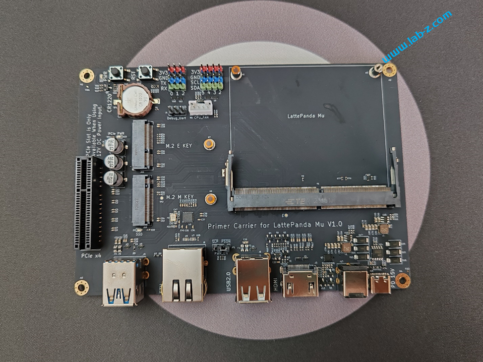
最近入手了LattePanda Mu ,这是一款微型 x86 计算模块,模块上带有 Intel N100 四核处理器、8GB LPDDR5 内存和 64GB 存储。搭配基础载板,后可以扩展出来
2个 USB 3.2 10Gbps 接口,1个千兆以太网,2个USB 2.0 ,1个HDMI 2.0,1个PCIEx1 接口。
供电方面可以通过USB Type-C(仅供电) 和12V DC 5.5×2.5mm 进行。
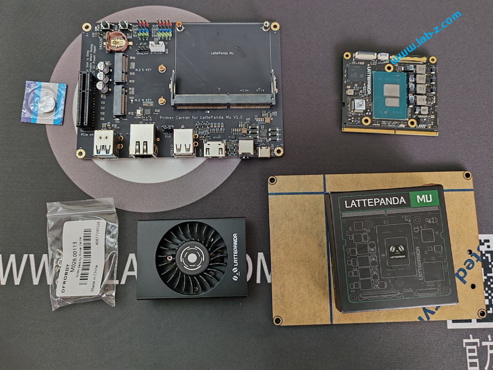
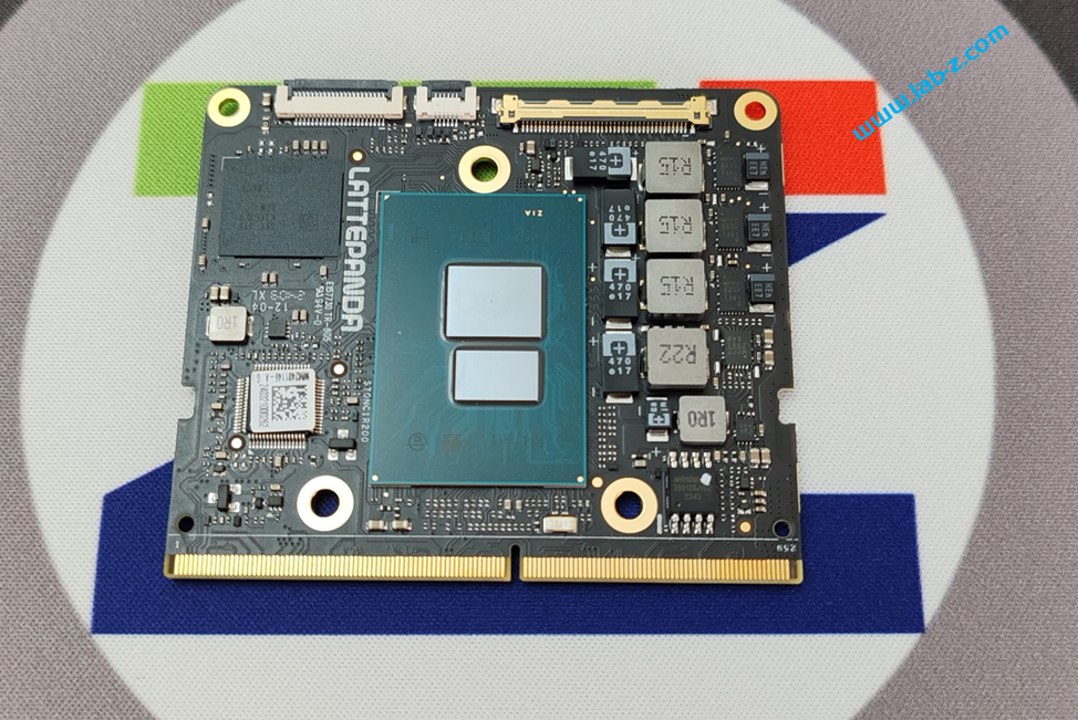
完整的系统分为2部分:核心板和载板。同样的核心板可以搭配不同的载板实现更强的扩展。
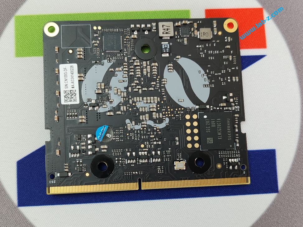
核心板非常迷你,接近信用卡尺寸:
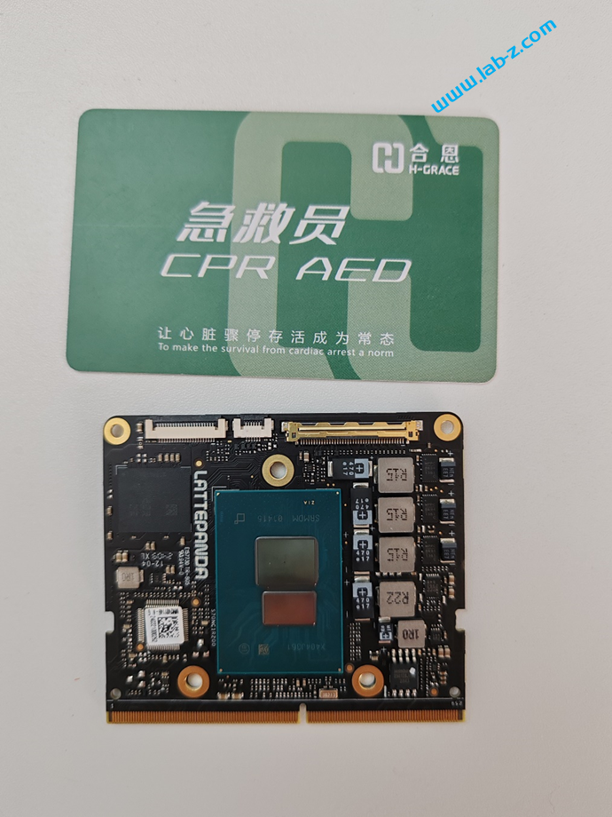
左上角的芯片是 LPDDR5 内存芯片,下面是 Super Io 芯片,中间是 Intel N100 芯片。
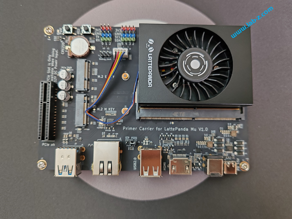
堆叠安装非常简单,在核心板上安装好风扇后即可插入载板中。
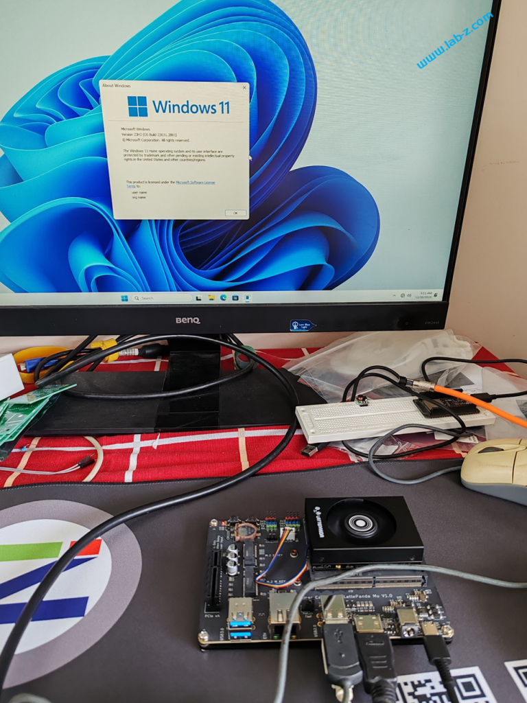
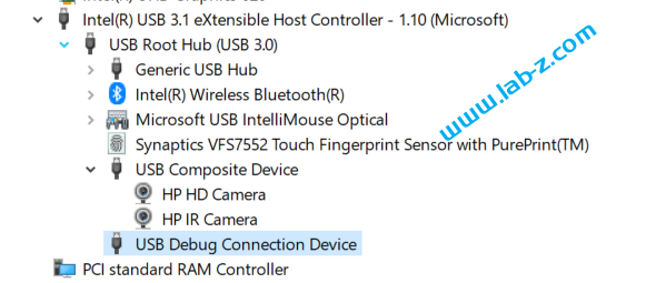
内置的 EMMC 已经预置了 Windows 11,连接好之后就可以开机上电。可以看出我使用笔记本的 TypeC 进行供电。
使用上非常简单,和普通的 X86 没有差别。
下面这个视频测试的是播放视频
https://www.bilibili.com/video/BV1gt421P7dB
这个视频是模拟器运行合金弹头
https://www.bilibili.com/video/BV1mx4y187r2
这款板子在设计上更倾向于开发板,后面会基于这个开发板来完成一些有趣的设计和研究。