这次介绍的项目是通过 FireBeetle ESP32 实现一个 8*16的单色LED矩阵,可以在上面实现一些简单的图形和动画效果。
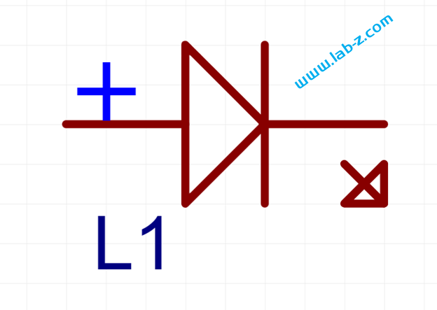
在开始之前,首先介绍LED 的静态驱动和动态驱动的概念。当我们在一个发光二极管两端加上一个电压的时候,发光二极管即可工作。理论上,如果驱动N个共阴极的LED那么需要N个提供正电压。这种带来一个问题,如果需要驱动大量的LED,那么就同样需要同样数量的引脚作为正极。对于单片机来说,会遇到IO引脚不够的问题。
这种直接驱动的方式称作“静态显示驱动”。与之相对,还可以通过构成矩阵的方式来进行驱动。以3×3的LED矩阵为例,通过6个IO 引脚可以驱动9个LED。
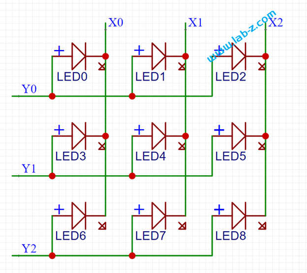
可以看到这种电路,我们可以一次性点亮一行或者一列上的LED,但是如果要点亮的位于不同的行列就会出现问题。例如:我们希望在矩阵上点亮LED0和LED6, 那么需要Y0、Y2为高,X0 为低,这种情况比较简单;但是如果需要同时点亮LED0和 LED4 问题就变得麻烦。因为 LED0 要求Y0 为高X0为低才能点亮,LED4 要求Y1为高X1为低,但是Y1为高X0为低时LED3也会同时亮起。因此,这里需要引入一个分时点亮的方法,比如,先设置Y0 为高X0为低点亮LED0,再设置Y0为低熄灭LED0,设置Y1为高X1为低点亮LED4,只要点亮速度足够快眼睛无法分辨出他们不是同时点亮的。这就是所谓的“动态扫描”。
如果使用 Arduino 编写代码,通常需要使用一个定时中断:
Void timerInterrupt()
{
熄灭上一次的行,点亮第x行
x=x+1
}
可以看出,这样的方法会使得程序复杂度上升,同样的,对于N 个灯需要根号N 个 IO。经过研究发现一个好玩的 IC: WCH 的 CH423。它是IC I/O 扩展芯片,功能如下【参考1】:
- 通过两线串行接口远程扩展出8 个通用输入输出引脚GPIO 和16 个通用输出引脚GPO。
- 内置电流驱动级,连续驱动电流不小于15mA,OC 引脚输出1/16 脉冲灌电流不小于120mA。
- 静态显示驱动方式支持24 只发光管LED 或者3 位共阳数码管。
- 分时动态扫描显示驱动方式支持128 只发光管LED 或者16 位共阴数码管,支持亮度控制。
- 双向I/O 引脚在输入方式下具有输入电平变化时产生中断的功能,中断输出低电平有效。
- 16 个通用输出引脚可以选择推挽输出或者开漏输出。
- 支持3V~5V 电源电压,支持低功耗睡眠,可以被输入电平变化唤醒。
- 高速2 线串行接口,时钟速度从0 到1MHz,兼容两线I2C 总线,节约引脚。
- 提供SDIP28 和SOP28 两种无铅封装,兼容RoHS。
这次的试验就使用这个芯片来实现一个 8×16的LED点阵。
首先进行电路设计:
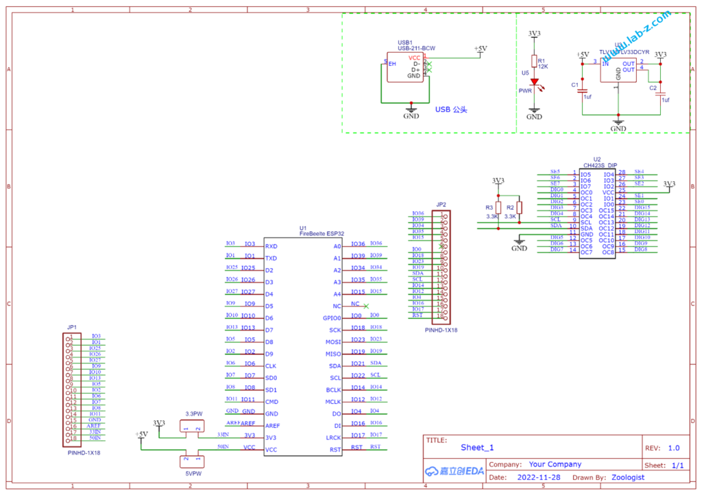
芯片是I2C 接口,控制线路非常简单:SCl和SDA就好了。CH423是SOP28封装,为了便于试验我从淘宝购买了一个SOP28转DIP的小PCB,焊接之后将CH423插入到PCB上。接下来是LED矩阵的设计:
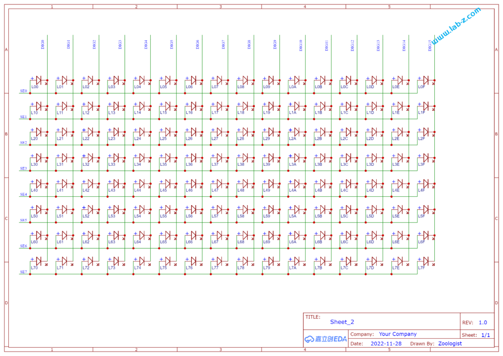
其中 SE[N] 信号能够输出高低电平,DEG[M] 只用作吸收电流使用。对CH423 发送命令,告知我现在要做动态扫描使用,然后告知SE[N]和DEG[M] 的组合即可。例如:告知SE1 输出高,DIG0 吸收电流和SE7输出高,DIG15吸收电流,之后芯片本身会动态控制,肉眼看起来就是 L00和L7F 点亮【参考2】。
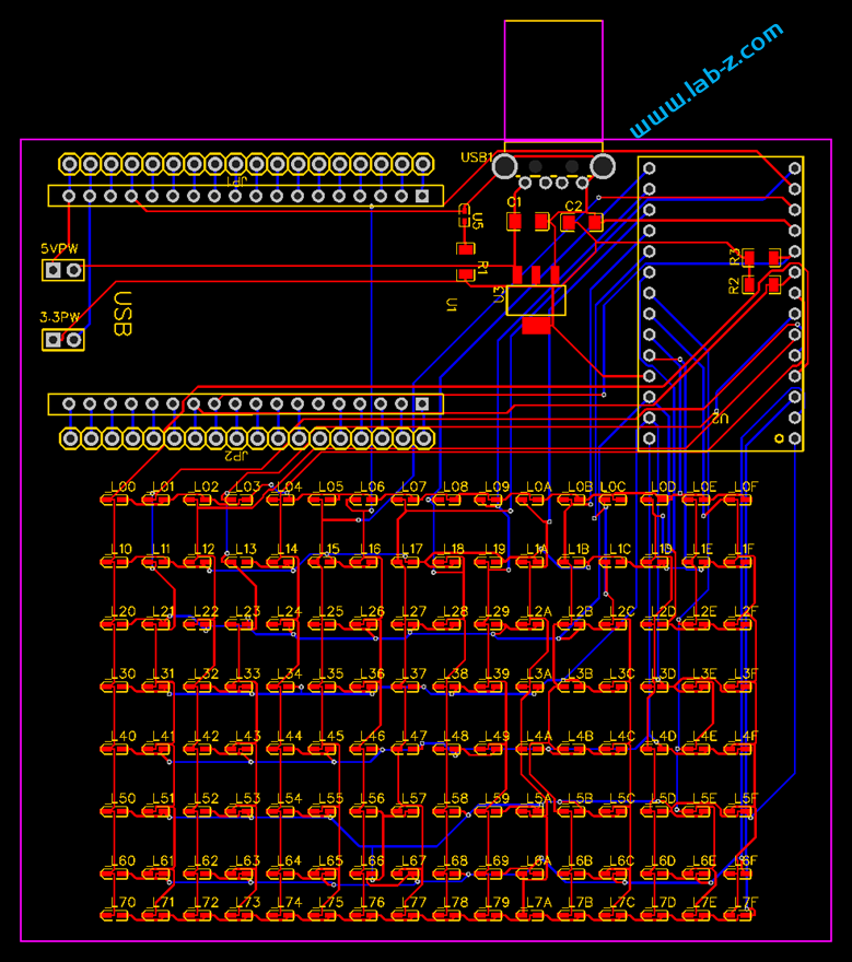
因为都是低速信号,没有太多限制,摆放好 LED后直接使用立创自动布线走的通即可。
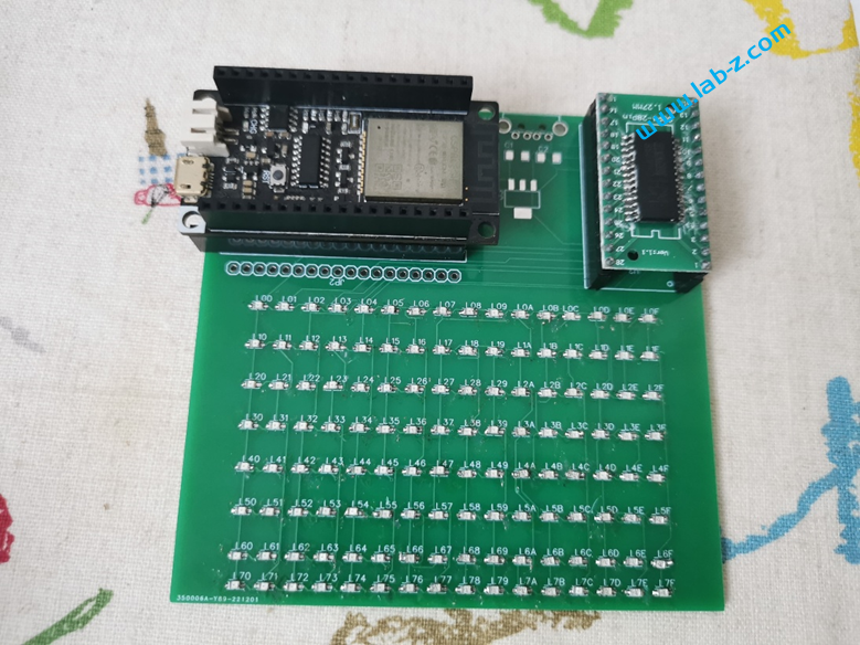
焊接后的样子:
编写一个测试代码如下:
#include <Wire.h>

// CH423接口定义
#define     CH423_I2C_ADDR1     0x20         // CH423的地址
#define     CH423_I2C_MASK      0x3E         // CH423的高字节命令掩码

#define CH423_SYSON1    0x0417    //开启自动扫描显示

unsigned char CH423_buf[16];    //定义16个数码管的数据映象缓存区
const unsigned char BCD_decode_tab[ 0x10 ] = { 0X3F, 0X06, 0X5B, 0X4F, 0X66, 0X6D, 0X7D, 0X07, 0X7F, 0X6F, 0X77, 0X7C, 0X58, 0X5E, 0X79, 0X71 };


void CH423_Write( uint32_t cmd )    // 写命令
{
  Serial.print("Address ");
  Serial.print(( unsigned char )(cmd >> 8), HEX);
  Serial.print("  command  ");
  Serial.print(( unsigned char ) (cmd & 0xff), HEX);
  Wire.beginTransmission (( unsigned char )(cmd >> 8));
  Wire.write( ( unsigned char ) (cmd & 0xff) );  // 发送数据
  // 结束总线
  if (Wire.endTransmission() == 0) {
    Serial.println(" I2C Success!");
  } else {
    Serial.println("I2C error!");
  }
}

// 向CH423输出数据或者操作命令,自动建立数据映象
void CH423_buf_write( uint32_t cmd )
{
  if ( cmd & 0x1000 )
  { // 加载数据的命令,需要备份数据到映象缓冲区
    CH423_buf[ (unsigned char)( cmd >> 8 ) & 0x0F ] = (unsigned char)( cmd & 0xFF );    // 备份数据到相应的映象单元
  }
  CH423_Write( cmd );    // 发出
}

void setup() {
  Serial.begin (115200);
  Wire.begin (21, 22);   // sda= GPIO_21 /scl= GPIO_22.
  /* INTENS [00-11]
     OD_EN 使能开漏
     X_INT 0x08
     DEC_H 0x04
     DEC_L 0x02
     IO_OE 0x01
  */
  CH423_buf_write( 0x2417 );
  /* OC_L_DAT  OC7-OC0 电平控制
  */
  CH423_buf_write( 0x2200 );
  /* OC_H_DAT  OC15-OC8 电平控制
  */
  CH423_buf_write( 0x2300 );

  // 初始化时保持全灭
  uint32_t i;
  for (i = 0; i < 16; i++) {
    CH423_buf_write(((0x30 + i) << 8) + 0x00);
  }
}

// 要显示的字符取模, DFRobot 字样
// 来自 https://www.zhetao.com/fontarray.html
const unsigned char bitmap_bit_bytes[] = {
  0b00000000, 0b00000000, 0b00000000, 0b00000000, 0b00000000, 0b00000000, 0b00000000,
  0b00000000, 0b00000000, 0b00000000, 0b00000000, 0b00000000, 0b00000000, 0b00000000,
  0b00000000, 0b00000000, 0b00000000, 0b00000000, 0b00000000, 0b00000000, 0b00000000,
  0b11111000, 0b11111100, 0b11111100, 0b00000000, 0b00000000, 0b00000000, 0b00000000,
  0b01000100, 0b01000010, 0b01000010, 0b00000000, 0b11000000, 0b00000000, 0b00000000,
  0b01000010, 0b01001000, 0b01000010, 0b00000000, 0b01000000, 0b00000000, 0b00010000,
  0b01000010, 0b01001000, 0b01000010, 0b00000000, 0b01000000, 0b00000000, 0b00010000,
  0b01000010, 0b01111000, 0b01111100, 0b00111100, 0b01011000, 0b00111100, 0b01111100,
  0b01000010, 0b01001000, 0b01001000, 0b01000010, 0b01100100, 0b01000010, 0b00010000,
  0b01000010, 0b01001000, 0b01001000, 0b01000010, 0b01000010, 0b01000010, 0b00010000,
  0b01000010, 0b01000000, 0b01000100, 0b01000010, 0b01000010, 0b01000010, 0b00010000,
  0b01000010, 0b01000000, 0b01000100, 0b01000010, 0b01000010, 0b01000010, 0b00010000,
  0b01000100, 0b01000000, 0b01000010, 0b01000010, 0b01100100, 0b01000010, 0b00010010,
  0b11111000, 0b11100000, 0b11100011, 0b00111100, 0b01011000, 0b00111100, 0b00001100,
  0b00000000, 0b00000000, 0b00000000, 0b00000000, 0b00000000, 0b00000000, 0b00000000,
  0b00000000, 0b00000000, 0b00000000, 0b00000000, 0b00000000, 0b00000000, 0b00000000,
};

// 显示一个动画效果
uint16_t buf[8] = {
  0b0100000000000000,
  0b0010000000000000,
  0b0001000000000000,
  0b0000100000000000,
  0b0000010000000000,
  0b0000100000000000,
  0b0001000000000000,
  0b0010000000000000,
};

void loop() {
  uint16_t i, j, m;
  char c, v;
  while (Serial.available()) {
    c = Serial.read();
    // 显示卡面定义的字符
    if (c == '1') {
      for (i = 0; i < 7 ; i++) { //一共有7个字符
        for (j = 0; j < 16; j++) { // 每个字符有16个1Byte数据
          CH423_buf_write( ((0x30 + j) << 8) + bitmap_bit_bytes[i + j * 7] );
        }
        delay(500);
      }
    }
    // 随机点亮测试
    if (c == '2') {
      for (i = 0; i < 16; i++) {
        for (j = 0; j < 16; j++) {
          CH423_buf_write( ((0x30 + j) << 8) + random(0, 256) );
        }
        delay(500);
      }
    }
    // 移动的动画效果
    if (c == '3') {
      for (m = 0; m < 32; m++) {
        // 显示 buf 定义的图形
        for (i = 0; i < 16; i++)
        {
          v = 0;
          for (j = 0; j < 8; j++) {
            if ((buf[j] & (1 << i)) == 0) {
              v = v << 1;
            }
            else {
              v = (v << 1) + 1;
            }
          }
          CH423_buf_write( ((0x30 + i) << 8) + v );
        }
        // 移动 buf 字符
        for (i = 0; i < 8; i++) {
            if ((buf[i]&1)!=0) {buf[i]=buf[i]|0x8000;}
            buf[i]=buf[i]>>1;
          }
        delay(100);


      }
    }
  }

}
根据串口输入,进行不同的测试:
- 输入1 会逐个显示 DFRobot 字样
- 输入2会随机点亮
- 输入3会显示一个方向的简单动画效果。
参考:
- http://www.wch.cn/products/CH423.html
- 这部分在DataSheet有描述 “8.2. 动态显示驱动 CH423 的动态显示驱动方式用于驱动 128 只 LED 或者 16 只共阴数码管,由 IO7~IO0 引脚分别驱动共阴数码管的各个段引脚(各数码管并联),由 OC15~OC0 引脚分别驱动各个共阴数码管的公共端。单片机在加载完所有字数据后,开启 DEC_L 和 DEC_H 控制位由 CH423 自动地进行分时动态显示扫描。如果只需要驱动 8 只数码管,那么可以只开启 DEC_L 或者 DEC_H 其中的一个控制位,剩余的另CH423 中文手册”
工作的测试视频