本文是根据作者对于 Modern Standby 的理解写成的,在某些概念上会和定义有冲突,希望读者特别注意如果有冲突以官方文档为准。
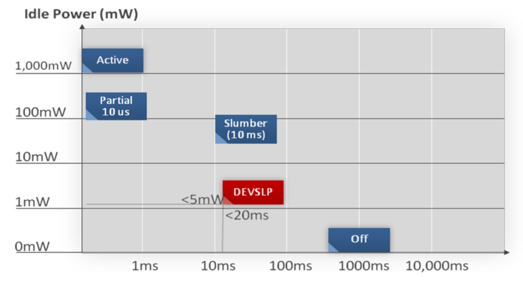
CPU 作为PC的大脑通常是最大的耗电大户。与之类似,人脑重量只占体重的2%,却会消耗整个身体所需能量的17%和氧气的20%。所以, CPU省电是整个PC系统降低功耗的关键。随着笔记本电脑的普及,如何降低功耗延长待机时间成为一个突出需求。在进一步介绍之前需要提及一下之前的休眠。在ACPI
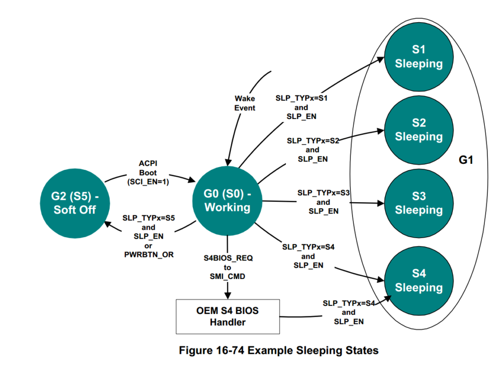
规范中定义了一些 PC 省电的状态。比如下图所示的S1
S3 和S4,当处于 S0 状态时,CPU处于工作状态:
如果能让CPU 在S0 的时候尽量降低功耗,那么可以节省出很多电力。此外,人们希望省电不要影响操作体验。为此,Intel 和微软携手一起推出了 Modern
Standby。据说这个概念来源自手机:对于用户来说,按下按键锁屏,屏幕黑掉之后系统会做一些动作来省电。具体的操作并不需要用户操心,相比PC用户,Legacy Sleep需要用户操作选择S1 S3 或者S4;手机用户按下按钮马上屏幕可以亮起来继续之前的使用。于是,Intel 和微软也希望能在PC上实现类似功能。比如,用户使用Windows平板电脑按下电源关闭屏幕就开始省电,再次按下就马上恢复使用,这样就能做到在不影响客户体验的情况下节省电力。
除了Modern
Standby(缩写 MS,还有些人会缩写成 MSB),该技术还可以被称作:Connected
Standby (缩写 CS),S0ix或者 Sleep S0。这里特别提一下用 Connected
Standby称呼 Modern Standby 功能并不恰当。Modern
Standby包括了2种,一种是 Connected
Standby,最主要的意思是睡眠的时候仍然联网,比如:收邮件。进入CS
之后后台仍然能够收邮件,唤醒之后马上就能看到新邮件。还有一种是 Disconnected Standby,就是睡眠的时候断网。很明显,因为有联网的操作,经常让系统睡的不踏实,人们也不知道睡眠的时候 Windows 究竟在后台干嘛。甚至很多时候 Windows后台升级操作会严重影响休眠,表面看着睡下去,但是实际上 CPU 并没有睡下去依然在工作。
[2] 更新源
进入目录c:\msys64\etc\pacman.d
在mirrorlist.msys的前面插入
Server = http://mirrors.ustc.edu.cn/msys2/msys/$arch
在mirrorlist.mingw32的前面插入
Server =
http://mirrors.ustc.edu.cn/msys2/mingw/i686
在mirrorlist.mingw64的前面插入
Server =
http://mirrors.ustc.edu.cn/msys2/mingw/x86_64
tar xvf qemu-4.2.0.tar (原文提供的是tar.xy 文件,使用这个命令tar
xvJf qemu-2.10.1.tar.xz)
cd ./qemu-2.10.1.tar
mkdir build
cd build
../configure
–prefix=/qemu –target-list=x86_64-softmmu –enable-sdl –enable-tools
make
make install
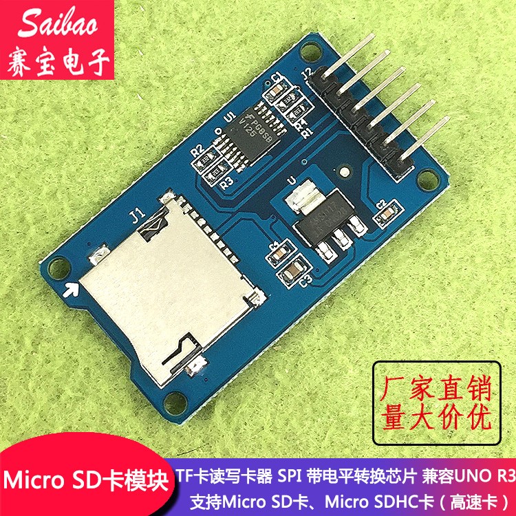
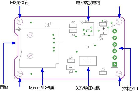
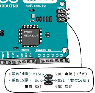
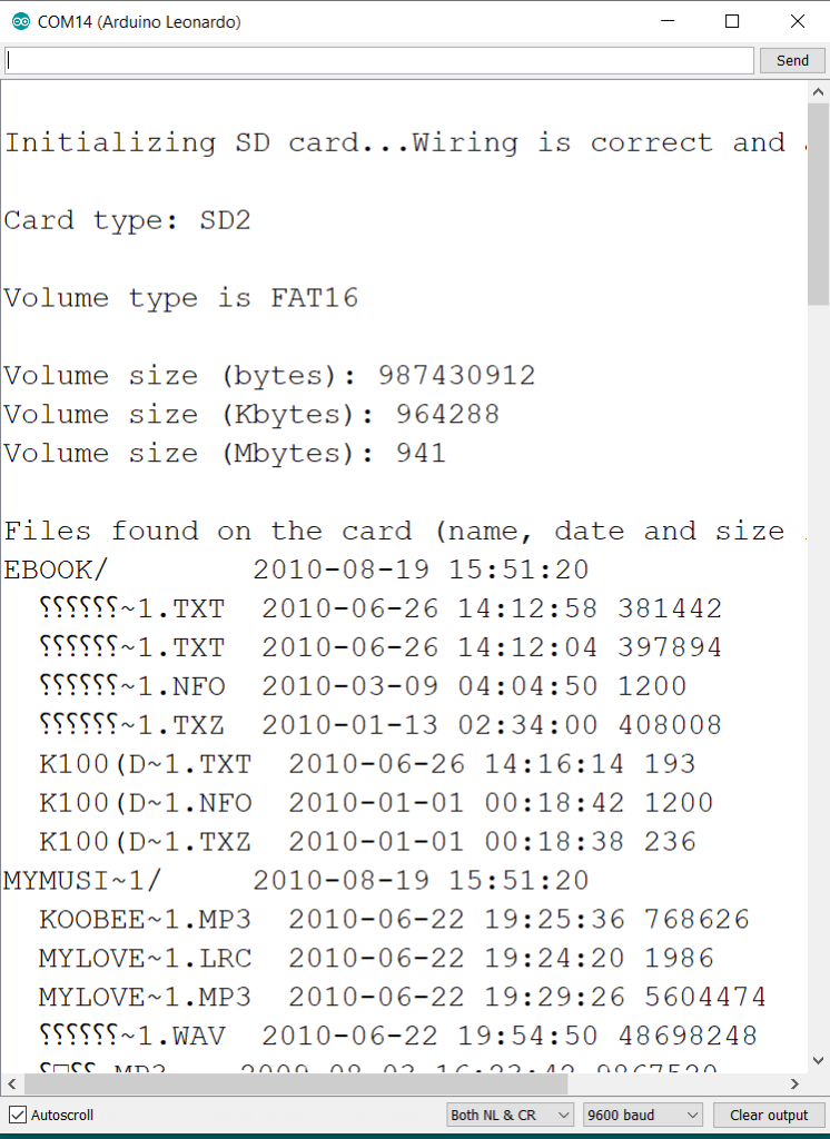
因此,需要将二者按照定义连接在一起,SD 卡模块上的CS接至D4 Pin。之后,运行 Example 中的CardInfo即可:
/*
  SD card test

 This example shows how use the utility libraries on which the'
 SD library is based in order to get info about your SD card.
 Very useful for testing a card when you're not sure whether its working or not.

 The circuit:
  * SD card attached to SPI bus as follows:
 ** MOSI - pin 11 on Arduino Uno/Duemilanove/Diecimila
 ** MISO - pin 12 on Arduino Uno/Duemilanove/Diecimila
 ** CLK - pin 13 on Arduino Uno/Duemilanove/Diecimila
 ** CS - depends on your SD card shield or module.
 		Pin 4 used here for consistency with other Arduino examples


 created  28 Mar 2011
 by Limor Fried
 modified 9 Apr 2012
 by Tom Igoe
 */
// include the SD library:
#include <SPI.h>
#include <SD.h>

// set up variables using the SD utility library functions:
Sd2Card card;
SdVolume volume;
SdFile root;

// change this to match your SD shield or module;
// Arduino Ethernet shield: pin 4
// Adafruit SD shields and modules: pin 10
// Sparkfun SD shield: pin 8
// MKRZero SD: SDCARD_SS_PIN
const int chipSelect = 4;

void setup() {
  // Open serial communications and wait for port to open:
  Serial.begin(9600);
  while (!Serial) {
    ; // wait for serial port to connect. Needed for native USB port only
  }


  Serial.print("\nInitializing SD card...");

  // we'll use the initialization code from the utility libraries
  // since we're just testing if the card is working!
  if (!card.init(SPI_HALF_SPEED, chipSelect)) {
    Serial.println("initialization failed. Things to check:");
    Serial.println("* is a card inserted?");
    Serial.println("* is your wiring correct?");
    Serial.println("* did you change the chipSelect pin to match your shield or module?");
    return;
  } else {
    Serial.println("Wiring is correct and a card is present.");
  }

  // print the type of card
  Serial.print("\nCard type: ");
  switch (card.type()) {
    case SD_CARD_TYPE_SD1:
      Serial.println("SD1");
      break;
    case SD_CARD_TYPE_SD2:
      Serial.println("SD2");
      break;
    case SD_CARD_TYPE_SDHC:
      Serial.println("SDHC");
      break;
    default:
      Serial.println("Unknown");
  }

  // Now we will try to open the 'volume'/'partition' - it should be FAT16 or FAT32
  if (!volume.init(card)) {
    Serial.println("Could not find FAT16/FAT32 partition.\nMake sure you've formatted the card");
    return;
  }


  // print the type and size of the first FAT-type volume
  uint32_t volumesize;
  Serial.print("\nVolume type is FAT");
  Serial.println(volume.fatType(), DEC);
  Serial.println();

  volumesize = volume.blocksPerCluster();    // clusters are collections of blocks
  volumesize *= volume.clusterCount();       // we'll have a lot of clusters
  volumesize *= 512;                            // SD card blocks are always 512 bytes
  Serial.print("Volume size (bytes): ");
  Serial.println(volumesize);
  Serial.print("Volume size (Kbytes): ");
  volumesize /= 1024;
  Serial.println(volumesize);
  Serial.print("Volume size (Mbytes): ");
  volumesize /= 1024;
  Serial.println(volumesize);


  Serial.println("\nFiles found on the card (name, date and size in bytes): ");
  root.openRoot(volume);

  // list all files in the card with date and size
  root.ls(LS_R | LS_DATE | LS_SIZE);
}


void loop(void) {

}
#include <Uefi.h>
#include <Library/UefiLib.h>
#include <Library/ShellCEntryLib.h>
/***
Print a welcoming message.
Establishes the main structure of the application.
@retval 0 The application exited normally.
@retval Other An error occurred.
***/
INTN
EFIAPI
ShellAppMain (
IN UINTN Argc,
IN CHAR16 **Argv
)
{
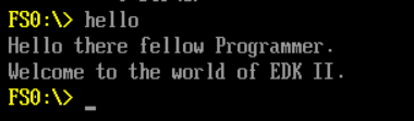
Print(L"Hello there fellow Programmer.\n");
Print(L"Welcome to the world of EDK II.\n");
return(0);
}
这个代码功能很简单,就是显示两行字符串。生成的代码为 8,160 (0x1FE0)bytes大小。
特别的,要在对应的INF文件中加入下面的语句保证生成 COD文件。
[BuildOptions]
  MSFT:*_*_X64_CC_FLAGS  = /FAsc /Od
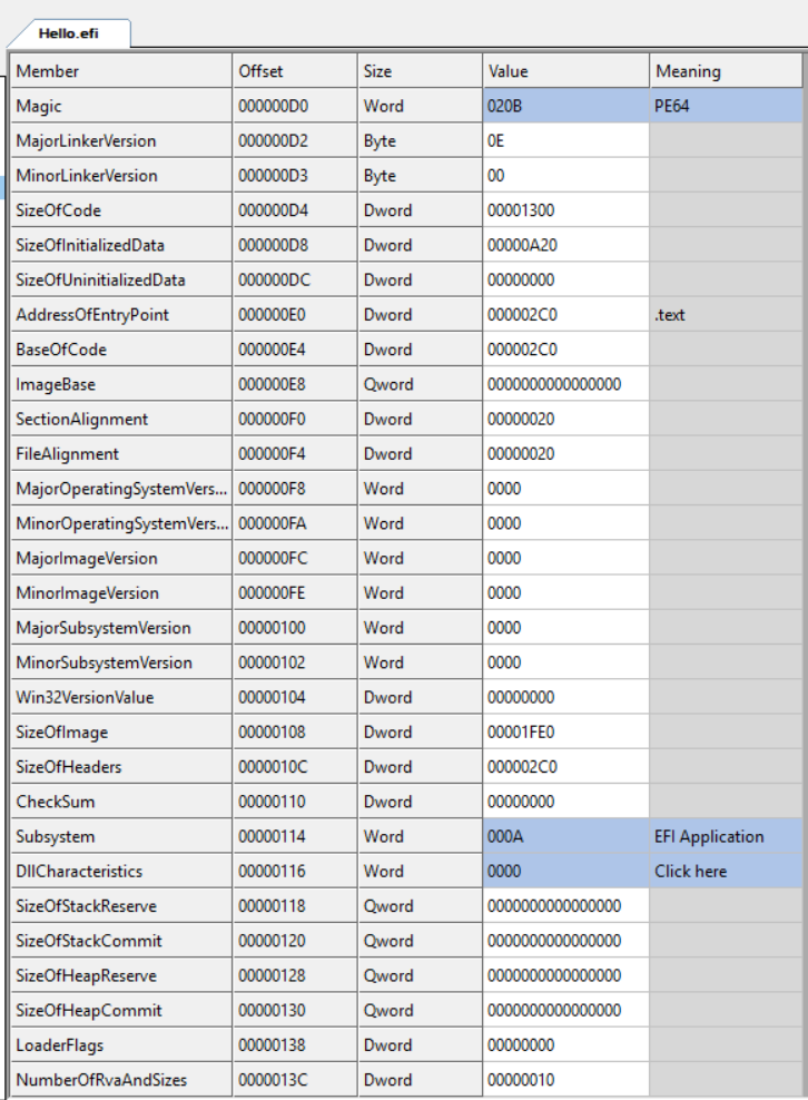
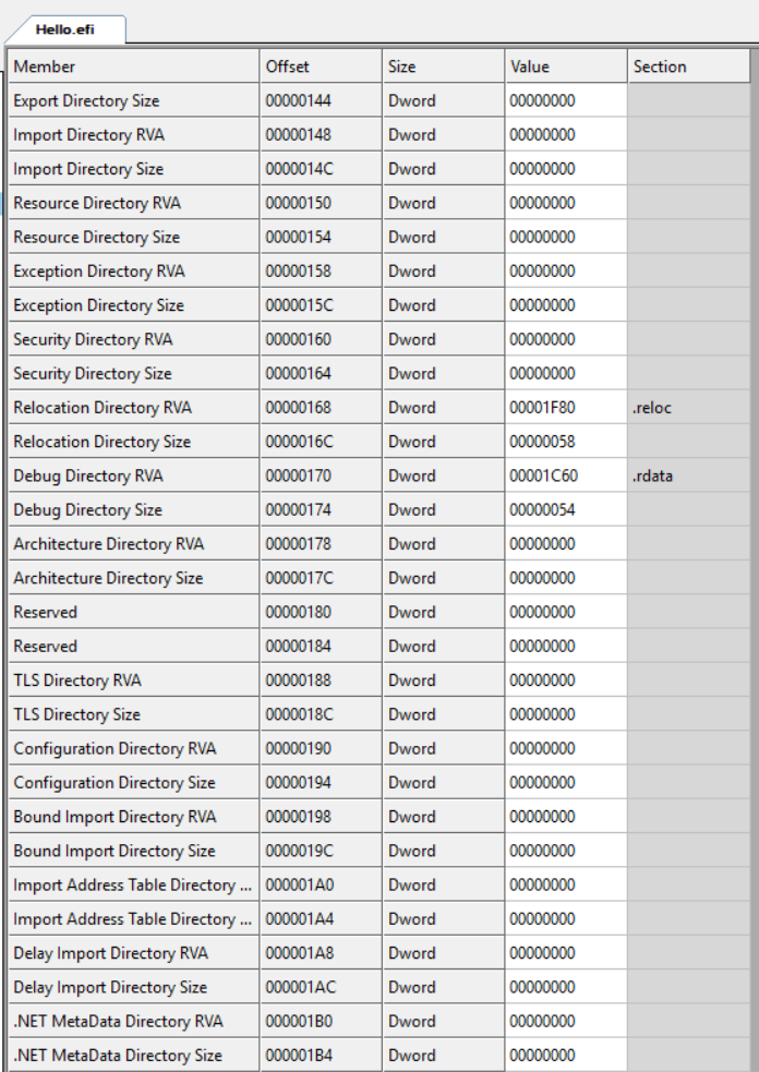
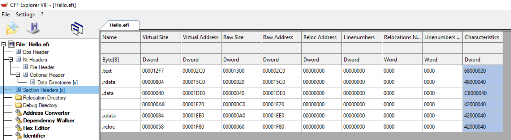
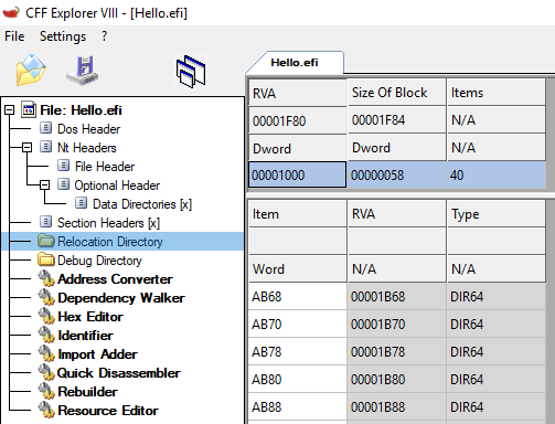
接下来使用 SFF 工具直接分析 EFI:
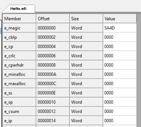
1.从 0 到 0x3C 是一个 Dos Header。这个只是作为兼容性的结构存在并没有任何功能。
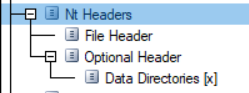
///
/// @attention
/// EFI_IMAGE_HEADERS64 is for use ONLY by tools.
///
typedef struct {
  UINT32                      Signature;
  EFI_IMAGE_FILE_HEADER       FileHeader;
  EFI_IMAGE_OPTIONAL_HEADER64 OptionalHeader;
} EFI_IMAGE_NT_HEADERS64;
///
/// Debug Directory Format.
///
typedef struct {
  UINT32  Characteristics;
  UINT32  TimeDateStamp;
  UINT16  MajorVersion;
  UINT16  MinorVersion;
  UINT32  Type;
  UINT32  SizeOfData;
  UINT32  RVA;           ///< The address of the debug data when loaded, relative to the image base.
  UINT32  FileOffset;    ///< The file pointer to the debug data.
} EFI_IMAGE_DEBUG_DIRECTORY_ENTRY;