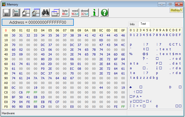
Start Length Name Class
0001:00000000 000012f7H .text$mn CODE
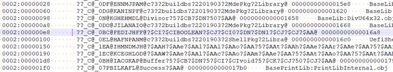
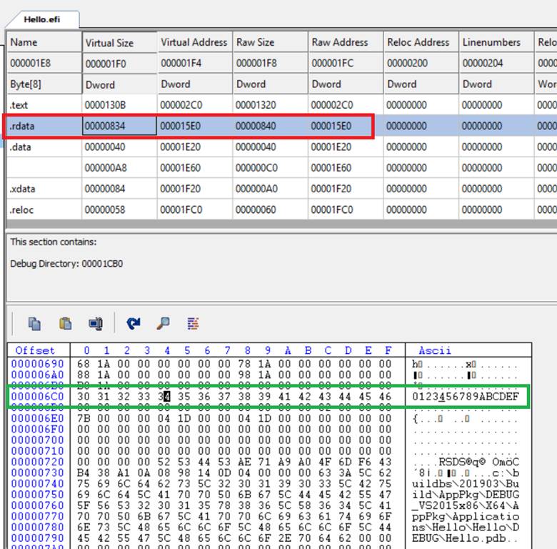
0002:00000000 000006f4H .rdata DATA
0002:000006f4 00000110H .rdata$zzzdbg DATA
0003:00000000 00000020H .data DATA
0003:00000020 00000020H .bss DATA
0004:00000000 000000a8H .pdata DATA
0005:00000000 00000084H .xdata DATA
/**
  Internal function that convert a number to a string in Buffer.

  Print worker function that converts a decimal or hexadecimal number to an ASCII string in Buffer.

  @param  Buffer    Location to place the ASCII string of Value.
  @param  Value     The value to convert to a Decimal or Hexadecimal string in Buffer.
  @param  Radix     Radix of the value

  @return A pointer to the end of buffer filled with ASCII string.

**/
CHAR8 *
BasePrintLibValueToString (
  IN OUT CHAR8  *Buffer,
  IN INT64      Value,
  IN UINTN      Radix
  )
{
  UINT32  Remainder;

  //
  // Loop to convert one digit at a time in reverse order
  //
  *Buffer = 0;
  do {
    Value = (INT64)DivU64x32Remainder ((UINT64)Value, (UINT32)Radix, &Remainder);
    *(++Buffer) = mHexStr[Remainder];
  } while (Value != 0);

  //
  // Return pointer of the end of filled buffer.
  //
  return Buffer;
}
; reserve space for 2 arguments
sub rsp, 2 * 8
; rdx points to the EFI_SYSTEM_TABLE structure
; which is the 2nd argument passed to us by the UEFI firmware
; adding 64 causes rcx to point to EFI_SYSTEM_TABLE.ConOut
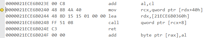
mov rcx, [rdx + 64]
; load the address of our string into rdx
lea rdx, [rel strHello]
; EFI_SYSTEM_TABLE.ConOut points to EFI_SIMPLE_TEXT_OUTPUT_PROTOCOL
; call OutputString on the value in rdx
call [rcx + EFI_SIMPLE_TEXT_OUTPUT_PROTOCOL.OutputString]
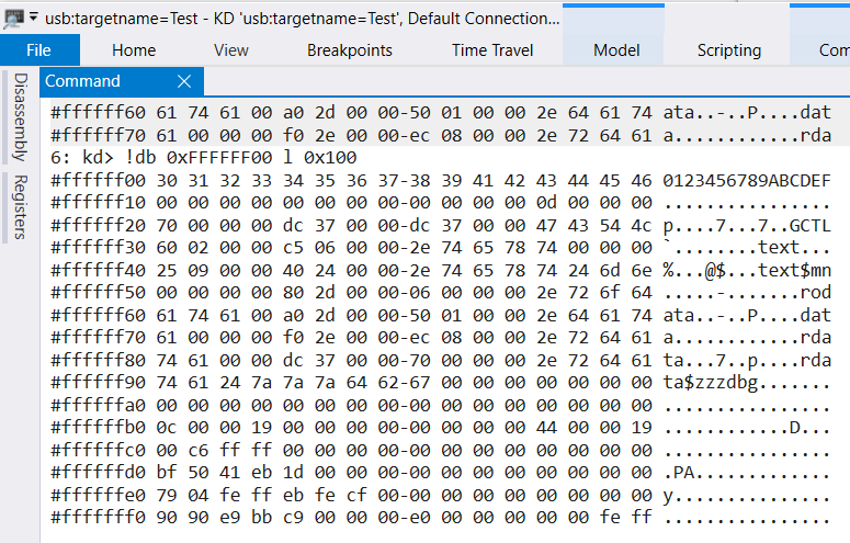
||0:6: kd> !rsdt
Sorry: Unable to get ACPI!AcpiInformation.
Searching for RSDP.*************************************************************************
***                                                                   ***
***                                                                   ***
***    Either you specified an unqualified symbol, or your debugger   ***
***    doesn't have full symbol information.  Unqualified symbol      ***
***    resolution is turned off by default. Please either specify a   ***
***    fully qualified symbol module!symbolname, or enable resolution ***
***    of unqualified symbols by typing ".symopt- 100". Note that     ***
***    enabling unqualified symbol resolution with network symbol     ***
***    server shares in the symbol path may cause the debugger to     ***
***    appear to hang for long periods of time when an incorrect      ***
***    symbol name is typed or the network symbol server is down.     ***
***                                                                   ***
***    For some commands to work properly, your symbol path           ***
***    must point to .pdb files that have full type information.      ***
***                                                                   ***
***    Certain .pdb files (such as the public OS symbols) do not      ***
***    contain the required information.  Contact the group that      ***
***    provided you with these symbols if you need this command to    ***
***    work.                                                          ***
***                                                                   ***
***    Type referenced: hal!_RSDT_32                                  ***
***                                                                   ***
*************************************************************************
.........................................0x0effe0: Read 0x000020 of 0x000024 bytes
Could not locate the RSDT pointer