带着问题进行学习是掌握一门技术非常有效的方法。
https://hdlbits.01xz.net/ 网站提供了 Verilog 的一些题目,有兴趣的朋友可以尝试进行练习。同时这个网站在提供 Verilog 基础语法教程的同时,还能够在线仿真你的 Verilog 模块,将你的输出与正确的时序比较。
如果你在解题时遇到问题,还可以在知乎“HDLBits 中文导学”专栏中看到解析(比如我经常无法理解题目意思),还可以在评论中参加讨论。
带着问题进行学习是掌握一门技术非常有效的方法。
https://hdlbits.01xz.net/ 网站提供了 Verilog 的一些题目,有兴趣的朋友可以尝试进行练习。同时这个网站在提供 Verilog 基础语法教程的同时,还能够在线仿真你的 Verilog 模块,将你的输出与正确的时序比较。
如果你在解题时遇到问题,还可以在知乎“HDLBits 中文导学”专栏中看到解析(比如我经常无法理解题目意思),还可以在评论中参加讨论。
最近研究了一下 OVMF 项目的 Setup 首页界面,实现的方法挺有意思。
第一个问题,具体代码在什么地方,如果我想增加一行字应该如何实现。
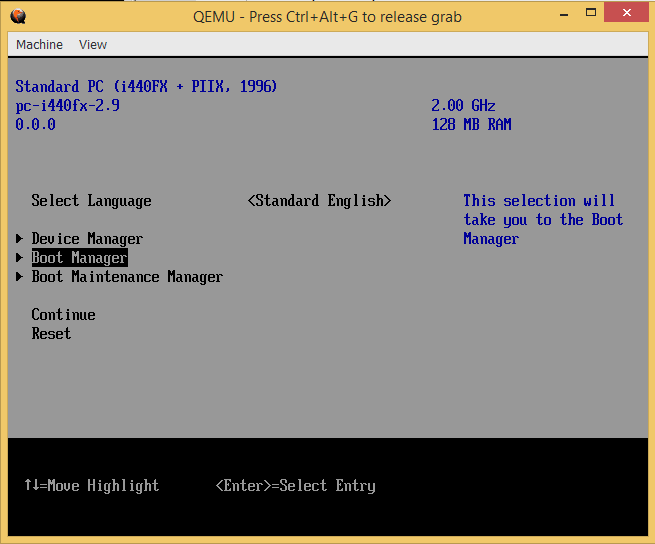
经过研究,相关代码在 MdeModulePkg\Application\UiApp\FrontPage.c 中。首先,在 FrontPageVfr.Vfr 定义了8个字符串变量,例如:STR_CUSTOMIZE_BANNER_LINE4_LEFT。 在首页上面左右各有4个。在 UpdateFrontPageBannerStrings() 函数中动态填充这些字符串。例如:从 SMBIOS 中取得CPU 信息显示出来:
    if ((Record->Type == SMBIOS_TYPE_PROCESSOR_INFORMATION) && !FoundCpu) {
      Type4Record = (SMBIOS_TABLE_TYPE4 *) Record;
      //
      // The information in the record should be only valid when the CPU Socket is populated.
      //
      if ((Type4Record->Status & SMBIOS_TYPE4_CPU_SOCKET_POPULATED) == SMBIOS_TYPE4_CPU_SOCKET_POPULATED) {
        StrIndex = Type4Record->ProcessorVersion;
        GetOptionalStringByIndex ((CHAR8*)((UINT8*)Type4Record + Type4Record->Hdr.Length), StrIndex, &NewString);
        UiCustomizeFrontPageBanner (2, TRUE, &NewString);
        HiiSetString (gFrontPagePrivate.HiiHandle, STRING_TOKEN (STR_FRONT_PAGE_CPU_MODEL), NewString, NULL);
        FreePool (NewString);

        ConvertProcessorToString(Type4Record->CurrentSpeed, 6, &NewString);
        UiCustomizeFrontPageBanner (2, FALSE, &NewString);
        HiiSetString (gFrontPagePrivate.HiiHandle, STRING_TOKEN (STR_FRONT_PAGE_CPU_SPEED), NewString, NULL);
        FreePool (NewString);

        FoundCpu = TRUE;
      }
    }
知道了上面的实现,如果想实现增加一行字符串,实现非常简单:在 FrontPageStrings.uni 文件中修改字符串增加内容即可:
#string STR_CUSTOMIZE_BANNER_LINE4_LEFT  #language en-US  "www.lab-z.com"
                                         #language fr-FR  ""
运行结果:

第二个问题,研究一下BIOS 版本号的显示。取得的方法非常类似,同样的文件中,代码如下:
    if (Record->Type == SMBIOS_TYPE_BIOS_INFORMATION) {
      Type0Record = (SMBIOS_TABLE_TYPE0 *) Record;
      StrIndex = Type0Record->BiosVersion;
      GetOptionalStringByIndex ((CHAR8*)((UINT8*)Type0Record + Type0Record->Hdr.Length), StrIndex, &NewString);

      FirmwareVersionString = (CHAR16 *) PcdGetPtr (PcdFirmwareVersionString);
      if (*FirmwareVersionString != 0x0000 ) {
        FreePool (NewString);
        NewString = (CHAR16 *) PcdGetPtr (PcdFirmwareVersionString);
        UiCustomizeFrontPageBanner (3, TRUE, &NewString);
        HiiSetString (gFrontPagePrivate.HiiHandle, STRING_TOKEN (STR_FRONT_PAGE_BIOS_VERSION), NewString, NULL);
      } else {
        UiCustomizeFrontPageBanner (3, TRUE, &NewString);
        HiiSetString (gFrontPagePrivate.HiiHandle, STRING_TOKEN (STR_FRONT_PAGE_BIOS_VERSION), NewString, NULL);
        FreePool (NewString);
      }
    }
就是说,如果没有定义 PcdFirmwareVersionString 那么会从 SMBIOS 中抓取BIOS 版本显示出来。
在 \OvmfPkg\SmbiosPlatformDxe\SmbiosPlatformDxe.c 可以看到版本信息定义如下:
#define TYPE0_STRINGS \
  "EFI Development Kit II / OVMF\0"     /* Vendor */ \
  "0.0.0\0"                             /* BiosVersion */ \
  "02/06/2015\0"                        /* BiosReleaseDate */
可以通过直接修改上面代码的方式来实现修改版本号的目标。作为“寻常不走路”的有志青年,当然不会满足于使用这样的方式来修改版本号。下面介绍直接在二进制上修改这个版本号。

在 Build\OvmfX64\DEBUG_VS2015x86\FV\Ffs\4110465d-5ff3-4f4b-b580-24ed0d06747aSmbiosPlatformDxe 目录下,可以找到 4110465d-5ff3-4f4b-b580-24ed0d06747a.ffs 这个文件。打开文件可以搜索到 “1.2.3”字样:

尝试修改为 “4.5.6” 之后,再次使用之前介绍过的 GenFds ,生成 FD 文件,运行后就可以发现字符发生了变化:

这个实验也从侧面证明了 GenFds 是将需要的 FFS 文件集合在一起,然后压缩放入指定的文件中。
SleepStudy 是微软提供的一个查看功耗相关的功能,在所有的 Windows 10 中都有无需额外下载安装。使用方法:
1.打开 CMD 窗口,特别注意需要管理员权限;
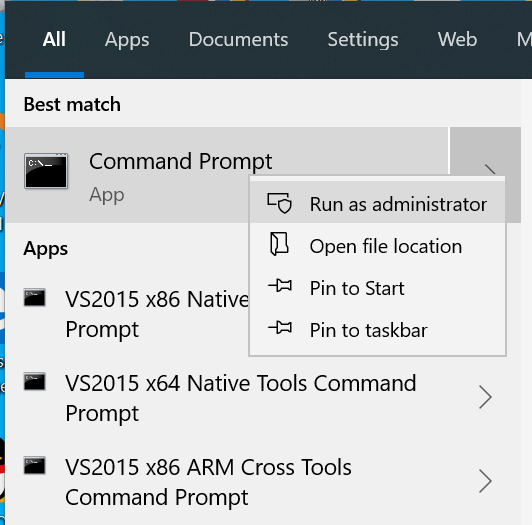
2.运行 powercfg /sleepstudy, 之后会将报告生成在一个 html 文件中

例如,下面就是一个 Pass 的结果,可以看到系统进入了 MS,98% 的 Software Residency和 Hardware Residency。

而这个是一个 Fail 的结果:Software Residency 为0 ,没有获得到 Hardware Residency。

这个报告在进行 Stress 测试的时候非常有用,能够一次性看到每一个Loop的结果,当然如果有问题,还需要运行 PHM 进行分析。
这个报告在进行 Stress 测试的时候非常有用,能够一次性看到每一个Loop的结果,当然如果有问题,还需要运行 PHM 进行分析。
特别注意:
2021年5月19日 最近又在测试 MS 功能,借此机会研究了一下清除 SleepStudy Log 的方法:清除 Event 是无效的,但是可以通过删除 Windows\system32\sleepStudy 目录下的内容来实现清除 SleepStudy Log 的目的。
当你使用 import YourFile.py 之后YourFile.py就会加载到内存中,即使你修改了本地的文件,再次调用也会是修改之前的代码。因此,这里需要用 reload 来强制重新加载。使用一个例子进行说明,首先编写一个简单的代码:
def Test():
print(“Test Script from labz”)
下面的步骤1导入上面的代码,然后运行 Test() 函数。接下来修改上面的代码,在输出的字符串末尾加入字符 2.步骤2中再次Import 然后运行,可以看到没有效果:

之后从 imp 中 import reload 函数(我的 python 是 3.8 , 这里同 2.X 的版本有差别)。再次 reload 代码之后可以看到结果有变化。

总结:可以通过 from imp import reload, 之后每次 reload 你需要的文件即可刷新。
LibC 是 EDK2 的一个库,提供了标准 C 库的支持。这个库在 VS2015 + EDK202008 的组合下工作正常,但是在 VS2019 下就会遇到一些问题,本文将介绍如何解决之。完成的目标是:完整编译 LibC 提供的 AppPkg 。LibC 可以在 https://github.com/tianocore/edk2-libc 下载到,打开之后内容如下:

解压三个目标到 EDK202008 后即可开始编译。
使用 “x86 Native Tools Command Prompt for VS2019”

命令
之后就遇到了第一个错误:
“Socket.c
c:\buildbs\edk202008\StdLib\EfiSocketLib\Socket.c(573): error C2220: the following warning is treated as an error
c:\buildbs\edk202008\StdLib\EfiSocketLib\Socket.c(573): warning C4459: declaration of 'errno' hides global declaration
c:\buildbs\edk202008\StdLib\Include\errno.h(43): note: see declaration of 'errno'
c:\buildbs\edk202008\StdLib\EfiSocketLib\Socket.c(1337): warning C4459: declaration of 'errno' hides global declaration
c:\buildbs\edk202008\StdLib\Include\errno.h(43): note: see declaration of 'errno'
c:\buildbs\edk202008\StdLib\EfiSocketLib\Socket.c(1480): warning C4459: declaration of 'errno' hides global declaration
c:\buildbs\edk202008\StdLib\Include\errno.h(43): note: see declaration of 'errno'
c:\buildbs\edk202008\StdLib\EfiSocketLib\Socket.c(1892): warning C4459: declaration of 'errno' hides global declaration
c:\buildbs\edk202008\StdLib\Include\errno.h(43): note: see declaration of 'errno'
c:\buildbs\edk202008\StdLib\EfiSocketLib\Socket.c(2754): warning C4459: declaration of 'errno' hides global declaration
c:\buildbs\edk202008\StdLib\Include\errno.h(43): note: see declaration of 'errno'
c:\buildbs\edk202008\StdLib\EfiSocketLib\Socket.c(2974): warning C4459: declaration of 'errno' hides global declaration
c:\buildbs\edk202008\StdLib\Include\errno.h(43): note: see declaration of 'errno'
NMAKE : fatal error U1077: '"C:\Program Files (x86)\Microsoft Visual Studio\2019\Enterprise\VC\Tools\MSVC\14.26.28801\bin\Hostx86\x64\cl.exe"' : return code '0x2'
Stop.”
解决方法是:在 StdLib.inc 末尾添加下面的内容:
# Temporarily restrict compiler warnings to those produced by VS2012.
  # Code that fails when these flags are removed will have to be rewritten
  # in order to pass.  This may be as simple as renaming an object, but may
  # require more significant changes.
    MSFT:*_VS2015_*_CC_FLAGS          = /Wv:11
    MSFT:*_VS2015x86_*_CC_FLAGS       = /Wv:11
    MSFT:*_VS2015xASL_*_CC_FLAGS      = /Wv:11
    MSFT:*_VS2015x86xASL_*_CC_FLAGS   = /Wv:11

#LABZ_Start
  # Temporarily restrict compiler warnings to those produced by VS2012.
  # Code that fails when these flags are removed will have to be rewritten
  # in order to pass.  This may be as simple as renaming an object, but may
  # require more significant changes.
    MSFT:*_VS2019_*_CC_FLAGS          = /Wv:11
    MSFT:*_VS2019x86_*_CC_FLAGS       = /Wv:11
    MSFT:*_VS2019xASL_*_CC_FLAGS      = /Wv:11
    MSFT:*_VS2019x86xASL_*_CC_FLAGS   = /Wv:11
#LABZ_End
再次编译会遇到下面这个这个错误:
        "C:\Program Files (x86)\Microsoft Visual Studio\2019\Enterprise\VC\Tools\MSVC\14.26.28801\bin\Hostx86\x64\link.exe" /OUT:c:\buildbs\edk202008\Build\AppPkg\DEBUG_VS2019\X64\AppPkg\Applications\Sockets\OobTx\OobTx\DEBUG\OobTx.dll /NOLOGO /NODEFAULTLIB /IGNORE:4001 /IGNORE:4281 /OPT:REF /OPT:ICF=10 /MAP /ALIGN:32 /SECTION:.xdata,D /SECTION:.pdata,D /Machine:X64 /LTCG /DLL /ENTRY:_ModuleEntryPoint /SUBSYSTEM:EFI_BOOT_SERVICE_DRIVER /SAFESEH:NO /BASE:0 /DRIVER /DEBUG /WHOLEARCHIVE  @c:\buildbs\edk202008\Build\AppPkg\DEBUG_VS2019\X64\AppPkg\Applications\Sockets\OobTx\OobTx\OUTPUT\static_library_files.lst
LibGdtoa.lib(ldtoa.obj) : error LNK2001: unresolved external symbol __fpclassifyd
BsdSocketLib.lib(res_send.obj) : error LNK2001: unresolved external symbol inet_ntoa
BsdSocketLib.lib(res_mkupdate.obj) : error LNK2001: unresolved external symbol inet_aton
BsdSocketLib.lib(ns_print.obj) : error LNK2001: unresolved external symbol inet_ntop
BsdSocketLib.lib(getnetbyht.obj) : error LNK2001: unresolved external symbol inet_network
c:\buildbs\edk202008\Build\AppPkg\DEBUG_VS2019\X64\AppPkg\Applications\Sockets\OobTx\OobTx\DEBUG\OobTx.dll : fatal error LNK1120: 5 unresolved externals
NMAKE : fatal error U1077: '"C:\Program Files (x86)\Microsoft Visual Studio\2019\Enterprise\VC\Tools\MSVC\14.26.28801\bin\Hostx86\x64\link.exe"' : return code '0x460'
Stop.
build.py...
 : error 7000: Failed to execute command
        C:\Program Files (x86)\Microsoft Visual Studio\2019\Enterprise\VC\Tools\MSVC\14.26.28801\bin\Hostx86\x86\nmake.exe /nologo tbuild [c:\buildbs\edk202008\Build\AppPkg\DEBUG_VS2019\X64\AppPkg\Applications\Sockets\OobTx\OobTx]


build.py...
 : error 7000: Failed to execute command
        C:\Program Files (x86)\Microsoft Visual Studio\2019\Enterprise\VC\Tools\MSVC\14.26.28801\bin\Hostx86\x86\nmake.exe /nologo tbuild [c:\buildbs\edk202008\Build\AppPkg\DEBUG_VS2019\X64\AppPkg\Applications\Sockets\DataSink\DataSink]


build.py...
 : error F002: Failed to build module
        c:\buildbs\edk202008\AppPkg\Applications\Sockets\OobTx\OobTx.inf [X64, VS2019, DEBUG]
解决方法是修改Conf/tools_def.txt 文件,注释掉一行。对于/WHOLEARCHIVE 这个参数的解释,可以在【参考1】看到,似乎是要求编译过程中把所有的可能的 OBJ 都编译一次?
*_VS2019_*_MAKE_FLAGS      = /nologo
*_VS2019_*_SLINK_FLAGS     = /NOLOGO /LTCG
*_VS2019_*_APP_FLAGS       = /nologo /E /TC
*_VS2019_*_PP_FLAGS        = /nologo /E /TC /FIAutoGen.h
*_VS2019_*_VFRPP_FLAGS     = /nologo /E /TC /DVFRCOMPILE /FI$(MODULE_NAME)StrDefs.h
#LABZ *_VS2019_*_DLINK2_FLAGS    = /WHOLEARCHIVE
*_VS2019_*_ASM16_PATH      = DEF(VS2019_BIN_IA32)\ml.exe
*_VS2019_*_DEPS_FLAGS      = DEF(MSFT_DEPS_FLAGS)
##################
# ASL definitions
##################
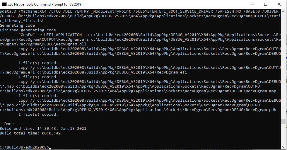
再次编译,就可以正常通过得到结果:
修改后的 Libc 可以在这里下载
链接: https://pan.baidu.com/s/1xCjiZ6_Shsa0tWOdRCjGrg 提取码: k6n2
感觉目前 EDK2 对于 VS2019 的支持还是有问题的,对于有编译需求的朋友,我依然建议使用 VS2015。
参考:
/WHOLEARCHIVE (Include All Library Object Files)
Force the linker to include all object files in the static library in the linked executable.
Syntax
/WHOLEARCHIVE
/WHOLEARCHIVE:library
Arguments
library
An optional pathname to a static library. The linker includes every object file from this library.
Remarks
The /WHOLEARCHIVE option forces the linker to include every object file from either a specified static library, or if no library is specified, from all static libraries specified to the LINK command. To specify the /WHOLEARCHIVE option for multiple libraries, you can use more than one /WHOLEARCHIVE switch on the linker command line. By default, the linker includes object files in the linked output only if they export symbols referenced by other object files in the executable. The /WHOLEARCHIVE option makes the linker treat all object files archived in a static library as if they were specified individually on the linker command line.
The /WHOLEARCHIVE option can be used to re-export all the symbols from a static library. This allows you to make sure that all of your library code, resources, and metadata are included when you create a component from more than one static library. If you see warning LNK4264 when you create a static library that contains Windows Runtime components for export, use the /WHOLEARCHIVE option when linking that library into another component or app.
The /WHOLEARCHIVE option was introduced in Visual Studio 2015 Update 2.
最近在使用 SerialPort 类发送串口数据,惊奇的发现PC端程序发送 0xFF 对面(ESP32)只能收到 0x7F。但是用串口工具是可以正常发送的。于是针对这个问题进行研究。Baidu上说是因为奇偶校验导致的,我设置了无校验现象依旧。
查看 SerialPort 类发现它有一个 Encoding 属性,默认是ASCIIEncoding,一般来说,正经的 ASCII 是 0-128 就是0-0x7F,因此,直觉上这个问题是它导致的。最终在下面的页面搜索到了答案:
http://www.innovatic.dk/knowledg/SerialCOM/SerialCOM.htm
By default, strings and char’s are transmitted (not coded) as 7-bit ASCII where all characters above 127 are illegal and will be replaced with “?” (code 63) – even though you have defined 8 data bits! Therefore, you cannot use a string or char related method to send or read binary information (0-255) unless you change the encoding to something, which include all values up to 255 like:
   YourSerialPort.Encoding = System.Text.Encoding.GetEncoding(28591)  ' or
   YourSerialPort.Encoding = System.Text.Encoding.GetEncoding(1252)
于是按照上面的方法修改代码问题就得以解决。
编译产生 BIOS ROM的最后一个步骤是将 FV 打包,那么这个操作是在哪里?带着这个问题,以 OVMF 的 PKG 为例进行研究。
我们平时编译使用的是 BaseTools\Bin\Win32下面的 build.exe ,这个文件是使用 Python 转 EXE工具生成的。如果想研究 Build.exe 具体的代码,可以将 build.exe 改名或者删除,然后保证当前 path 中含有BaseTools\BinWrappers\WindowsLike 路径,这样调用 Built 时会直接使用目录下的 Build.bat,该批处理内容如下:
@setlocal
@set ToolName=%~n0%
@%PYTHON_HOME%\python.exe %BASE_TOOLS_PATH%\Source\Python\%ToolName%\%ToolName%.py %*
如果你调用 build就会使用 Python.exe 来执行BaseTools\Source\Python\build\build.py。特别提醒,我实验发现 Python38 会出现如下的错误:
except BaseException, X:
^
SyntaxError: invalid syntax
修正方法是更换为 Python27 的版本(他们可以共存)。另外,这个问题也可能是我使用的 EDK2 版本的问题(我实验环境是EDK2201911).
代码入口在 main中,可以通过加入下面2条语句做一个标记:
print("www.lab-z.com\n")
subprocess.call("pause",shell=True)
添加在代码中入口位置
## Tool entrance method
#
# This method mainly dispatch specific methods per the command line options.
# If no error found, return zero value so the caller of this tool can know
# if it's executed successfully or not.
#
#   @retval 0     Tool was successful
#   @retval 1     Tool failed
#
def Main():
测试结果:

代码中MyBuild.Launch()是具体执行 build 动作的地方:
        MyBuild = Build(Target, Workspace, Option)
        GlobalData.gCommandLineDefines['ARCH'] = ' '.join(MyBuild.ArchList)
        if not (MyBuild.LaunchPrebuildFlag and os.path.exists(MyBuild.PlatformBuildPath)):
            MyBuild.Launch()
实验确定对应代码:
    ## Launch the module or platform build
    #
    def Launch(self):
        if not self.ModuleFile:
            if not self.SpawnMode or self.Target not in ["", "all"]:
                self.SpawnMode = False
                self._BuildPlatform()
            else:
                self._MultiThreadBuildPlatform()
            self.CreateGuidedSectionToolsFile()
        else:
            self.SpawnMode = False
            self._BuildModule()
self._MultiThreadBuildPlatform() 这里会完成所有的动作.这个函数在同一个文件中:
    ## Build a platform in multi-thread mode
    #
    def _MultiThreadBuildPlatform(self):
        SaveFileOnChange(self.PlatformBuildPath, '# DO NOT EDIT \n# FILE auto-generated\n', False)
我们的目标是找到最后将 FV 打包的过程,在代码中下面的位置加入 Pause 可以正常停下来,所以确定这个是我们目标动作的位置。
                    if self.Fdf:
    		print("www.lab-z.com\n")
subprocess.call("pause",shell=True)

                        #
                        # Generate FD image if there's a FDF file found
                        #
                        GenFdsStart = time.time()
                        LaunchCommand(Wa.GenFdsCommand, os.getcwd())

                        #
                        # Create MAP file for all platform FVs after GenFds.
                        #
                        self._CollectFvMapBuffer(MapBuffer, Wa, ModuleList)
                        self.GenFdsTime += int(round((time.time() - GenFdsStart)))
                    #
                    # Save MAP buffer into MAP file.
                    #
                    self._SaveMapFile(MapBuffer, Wa)
代码中加入下面两句输出具体调用的命令:
                        print("[%s]\n" % Wa.GenFdsCommand)
                        print("[%s]\n" % os.getcwd())
                        subprocess.call("pause",shell=True)

测试,在编译环境下输入下面的 command, 可以实现生成 OVMF.fd:
GenFds -f c:\buildbs\i2c\OvmfPkg\OvmfPkgX64.fdf --conf=c:\buildbs\i2c\conf -o c:\buildbs\i2c\Build\OvmfX64\DEBUG_VS2015x86 -t VS2015x86 -b DEBUG -p c:\buildbs\i2c\OvmfPkg\OvmfPkgX64.dsc -a X64 -D "EFI_SOURCE=c:\\buildbs\\i2c\\edkcompatibilitypkg" -D "EDK_SOURCE=c:\\buildbs\\i2c\\edkcompatibilitypkg" -D "TOOL_CHAIN_TAG=VS2015x86" -D "TOOLCHAIN=VS2015x86" -D "TARGET=DEBUG" -D "FAMILY=MSFT" -D "WORKSPACE=c:\\buildbs\\i2c" -D "EDK_TOOLS_PATH=c:\\buildbs\\i2c\\basetools" -D "ARCH=X64" -D "ECP_SOURCE=c:\\buildbs\\i2c\\edkcompatibilitypkg"
结论:build 过程中的最后一段是调用 GenFds 来生成 BIOS 的 FD (或者叫做 ROM)文件。
之前我一直使用 WinHex作为十六进制编译器,但是WinHex 是收费的,经过研究找到了 HxD 这款软件,它是免费的十六进制编辑软件,主页在 https://mh-nexus.de/en/hxd/ 经过一段时间的使用(主要是用于 ROM 文件的分析),感觉挺好用,有需要的朋友可以试试。
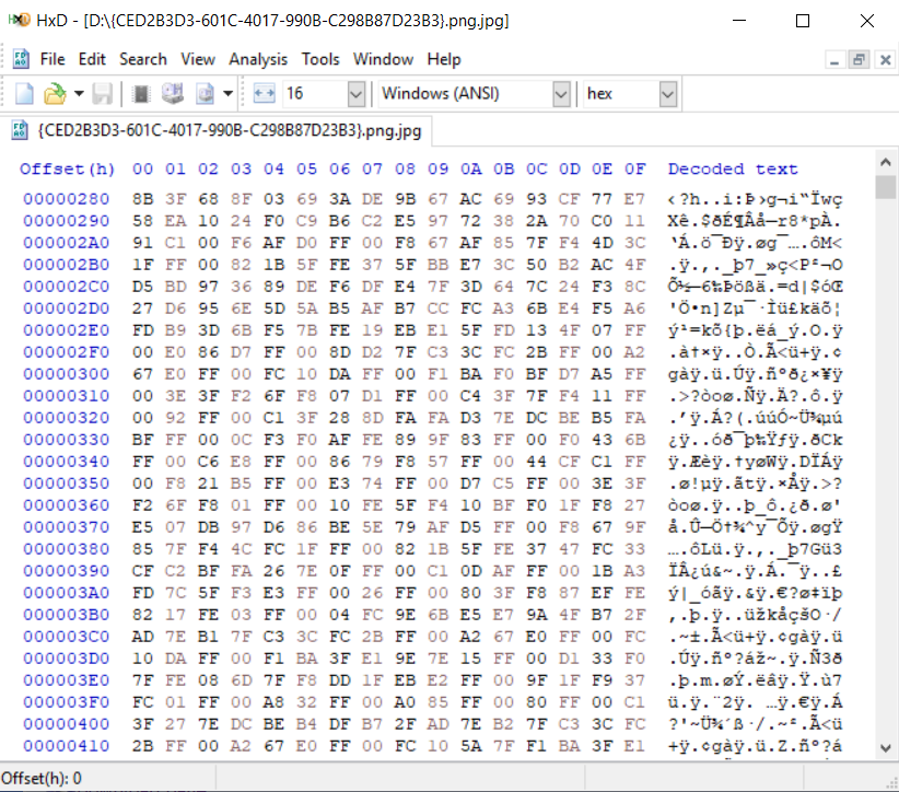
它提供了如下功能:
CSME 和BIOS 并没有多少关系,但是因为同属 Firmware,所以出了问题都会首先找BIOS工程师。对于大多数情况下,升级 CSME 都能解决问题。因此,BIOS工程师遇到的问题是:当前 CSME 是什么版本?通常的解决方法是进入BIOS Setup查看,更专业一点是在 Shell 或者Windows 下运行Intel提供的 MEInfo这个工具。但是对于单独的Binary 就无能为力了。
最近发现了一个开源工具,能够完成这个目标。项目地址是 https://github.com/platomav/MEAnalyzer
项目发布了2个版本: Python的源代码版本和转换为 EXE 的版本。对于大多数用户,个人推荐EXE版本,理由是:省事。
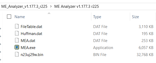
首先展示一下 EXE版本的使用,直接将要查看的Binary 推拽到EXE 上即可:
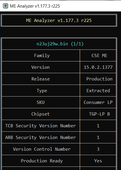
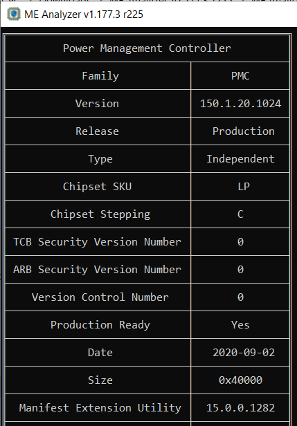
运行结果:
Python 版本的下载之后文件如下:
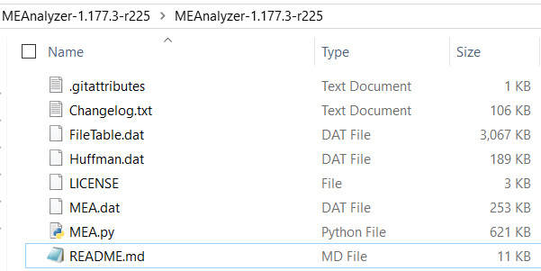
运行方法是打开 CMD 窗口后输入 mea.py + 文件名,运行结果和EXE版本的相同。但是这个代码需要3个额外的库 colorama ,crccheck和PLTable,可以在 https://pypi.org/ 找到。我在附件中提供了直接下载。Colorama 和crccheck是以 WHL 格式提供的。安装方法是将下载好的 WHL 文件放在 Python 安装后的 Scripts 目录下,然后使用 pip install 命令安装,示例如下:
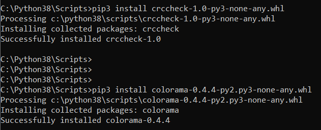
如果发生 pip3无法运行的情况,推荐卸载 Python 之后重新安装,安装时务必选中 PIP选项。
对于PLTable安装方法是解压后CMD窗口中使用 python setup.py install 进行安装:
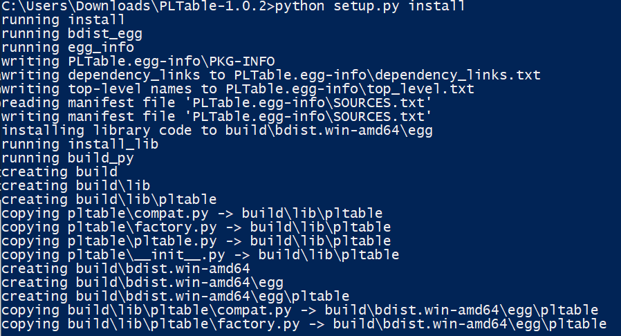
本文提到的文件可以在这里下载,推荐有兴趣的朋友试试
链接: https://pan.baidu.com/s/1GaDeaRWZU-hpwAnUx4mT5w 提取码: 3rz3
最近看资料了解到的一种内存的攻击方式,效果是能够翻转被攻击的内存区域 Bits,如果这个 Bits 正好是用于检查权限之类的,用这种方法就能获得更高的权限。
原理:RAM的制造精度越来越高,部件在物理层面上越来越小。既能在一块芯片上集成更大的内存容量,又能让各个内存单元之间不发生电磁干扰是非常难以做到的。这一情况使得对内存的单个区域进行的读写有可能干扰到邻近的区域,导致电流流入或流出邻近的内存单元。如果反复进行大量读写,有可能改变邻近内存单元的内容,使得0变成1,或者1变成0。这种现象被称为比特翻转(bitflipping),可被利用获取更高的权限。【参考1】
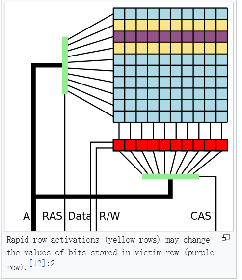
当然,从原理上来看触发Rowhammer漏洞非常简单,但成功地利用该漏洞有点难,因为内存中大多数的位是与攻击目标无关的,而这些无关位的翻转可能会导致内存破坏。想要成功地利用Rowhammer,攻击者必须能够诱使系统加载目标内存页到DRAM中与攻击者所有的物理内存行邻接的行中。【参考3】
在 MemTest86 的测试中,如果有遇到写入和读取有1Bit差别的failure,可以尝试在Setep 中打开 Enable RH Prevention 这个功能。
参考:
1.http://xilinx.eetrend.com/d6-xilinx/news/2016-10/10624.html 【DDR未解之谜】Row Hammer这么严重,知道如何解决吗?
2.https://www.zhihu.com/question/28666294 Row Hammer漏洞会有多大实质性影响?
3.https://blog.csdn.net/u013806583/article/details/53103714