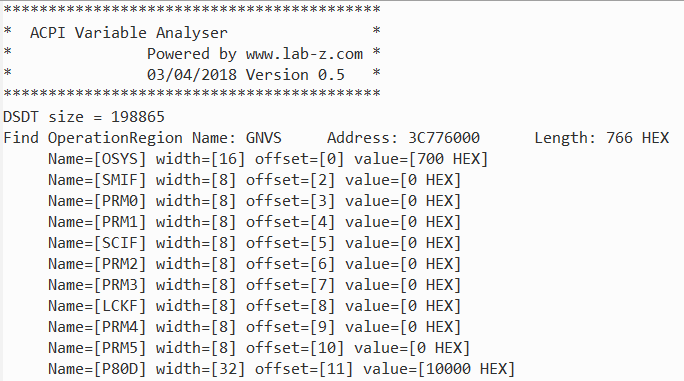
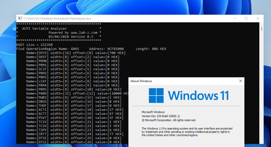
最新版本的 RU

本文提供的下载来自:https://firmwaresecurity.com/tag/ru-efi/

d8ec4-20171204183355-bmp

作者Blog 在: http://ruexe.blogspot.tw/ (需要翻墙)
Release 在 https://github.com/JamesAmiTw/ru-uefi

下载 5.20.0328

提起来这个工具的原因是有朋友给我留言说 RU 有查看 ACPI Table 的功能,虽然我几乎天天都在使用但是无印象,于是特地去找了验证一下,真的没有。不过这个版本和之前的相比增加了下面的功能,有需要的朋友可以直接使用,附件中有三个版本:32位、64位、DOS。

1.查看 UEFI Variable
2.AHCI MMIO
3.USB MMIO
4.Mass storage 设备的编辑
5.截图

最后特别感谢作者,来自 AMI 的 James Wang
======================================================================================================
2018年1月12日 来自微信的朋友“耳溫”,在公众号上留言,表示 ALT+F6可以实现 ACPI Table的读取,在此特别感谢指导

UEFI4BIOS_20180110_213822

Step to UEFI (136)哪里来的的 memset

最近编写一个非常简单的代码,遇到奇怪的问题,有兴趣的朋友可以先自己猜一下,答案在后面。
代码如下:

/** @file
    A simple, basic, application showing how the Hello application could be
    built using the "Standard C Libraries" from StdLib.

    Copyright (c) 2010 - 2011, Intel Corporation. All rights reserved.<BR>
    This program and the accompanying materials
    are licensed and made available under the terms and conditions of the BSD License
    which accompanies this distribution. The full text of the license may be found at
    http://opensource.org/licenses/bsd-license.

    THE PROGRAM IS DISTRIBUTED UNDER THE BSD LICENSE ON AN "AS IS" BASIS,
    WITHOUT WARRANTIES OR REPRESENTATIONS OF ANY KIND, EITHER EXPRESS OR IMPLIED.
**/
#include <Library/BaseLib.h>
#include <Uefi.h>
#include <Library/UefiLib.h>
#include <Library/PrintLib.h>
#include <Library/ShellCEntryLib.h>
#include <Protocol/EfiShell.h>
#include <Library/ShellLib.h>

void prt(IN UINT16 *p)
{
       UINT8   i;
        for (i=0;i<256;i++) {
           Print(L"%c",*p);
           p++;
        }
}
INTN
EFIAPI
ShellAppMain (
  IN UINTN Argc,
  IN CHAR16 **Argv
  )
{
        CHAR8   buffer[256];
        UINT16  i;
        
        for (i=0;i<256;i++) {
                buffer[i]='L';
        }
        prt((UINT16*)buffer);
        return 0;
}


错误信息如下:

“C:\Program Files (x86)\Microsoft Visual Studio 12.0\Vc\bin\x86_amd64\li
b.exe” /NOLOGO /LTCG /OUT:d:\udk2017\Build\AppPkg\DEBUG_VS2013x86\X64\AppPkg\App
lications\SimpleDemo\SimpleDemo\OUTPUT\wft.lib @d:\udk2017\Build\AppPkg\DEBUG_VS
2013×86\X64\AppPkg\Applications\SimpleDemo\SimpleDemo\OUTPUT\object_files.lst
“C:\Program Files (x86)\Microsoft Visual Studio 12.0\Vc\bin\x86_amd64\li
nk.exe” /OUT:d:\udk2017\Build\AppPkg\DEBUG_VS2013x86\X64\AppPkg\Applications\Sim
pleDemo\SimpleDemo\DEBUG\wft.dll /NOLOGO /NODEFAULTLIB /IGNORE:4001 /OPT:REF /OP
T:ICF=10 /MAP /ALIGN:32 /SECTION:.xdata,D /SECTION:.pdata,D /Machine:X64 /LTCG /
DLL /ENTRY:_ModuleEntryPoint /SUBSYSTEM:EFI_BOOT_SERVICE_DRIVER /SAFESEH:NO /BAS
E:0 /DRIVER /DEBUG @d:\udk2017\Build\AppPkg\DEBUG_VS2013x86\X64\AppPkg\Applicat
ions\SimpleDemo\SimpleDemo\OUTPUT\static_library_files.lst
Generating code
Finished generating code
UefiApplicationEntryPoint.lib(ApplicationEntryPoint.obj) : error LNK2001: unreso
lved external symbol memset
d:\udk2017\Build\AppPkg\DEBUG_VS2013x86\X64\AppPkg\Applications\SimpleDemo\Simpl
eDemo\DEBUG\wft.dll : fatal error LNK1120: 1 unresolved externals
NMAKE : fatal error U1077: ‘”C:\Program Files (x86)\Microsoft Visual Studio 12.0
\Vc\bin\x86_amd64\link.exe”‘ : return code ‘0x460’
Stop.

build…
: error 7000: Failed to execute command
C:\Program Files (x86)\Microsoft Visual Studio 12.0\Vc\bin\nmake.exe /no
logo tbuild [d:\udk2017\Build\AppPkg\DEBUG_VS2013x86\X64\AppPkg\Applications\Sim
pleDemo\SimpleDemo]

build…
: error F002: Failed to build module
d:\udk2017\AppPkg\Applications\SimpleDemo\SimpleDemo.inf [X64, VS2013x86
, DEBUG]

– Failed –
Build end time: 11:17:59, Dec.12 2017
Build total time: 00:00:12

上面就是完整的代码和现象,有兴趣的朋友可以琢磨一下,答案在下面。


kenan


刚开始看到错误提示我还非常疑惑”为啥没有具体错误信息“。仔细观察才发现错误信息是无法Link到 memset上。但是我的代码没有调用 memset。带着疑惑,我在 Inf 中刚加入 /FAcs /Od 准备查看汇编级代码。但是加入之后错误就会消失。
[BuildOptions]
MSFT:*_*_X64_CC_FLAGS = /FAcs /Od
再仔细研究,原来是 /Od 会让错误消失,接下来就简单了,比较只有 /FAcs 和带有 /Od的汇编代码,在 Simpledemo.cod 文件中找到了答案。左边是没有加入 /Od 的,右边是加入 /Od 的。这个参数的意思是关闭优化。比较打开和关闭优化的结果:

mms

因此,问题就清楚了,因为我的赋值是对 buffer[] 全部写入 “L”,所以编译器会自作主张的用memset 来对内存直接赋值,但是恰好我们没有定义 memset,所以就会出现错误。

介绍一个查看ACPI Table 的工具

Windows下查看 ACPI Table首推的工具当然是 RW_Everything。不过除此之外,今天又发现了一个工具,在 http://www.nirsoft.net/utils/firmware_tables_view.html。

我在 Windows 10 下面测试过,很好用。每种不足的是只列出值,并没有进一步的解析。有兴趣的朋友可以下载。

rdacpi

有32位和64位两个版本:

firmwaretablesview

firmwaretablesview-x64

从原理上说,这样的工具不是从内存中读取,所以使用的时候也无需管理员权限。后面有机会会仔细分析一下。

=======================================================================
2018年1月31日 1.01 版本发现一个 Bug: 如果系统中有多个 SSDT ,那么只能显示第一个。我给作者写邮件了,报告了这个问题。

器材:硕飞 SPI 烧写器

作为一名BIOS工程师,长期以来使用的都是 DediProg 推出的 SF 系列。比如,很多年来,我一直使用的是 SF100,售价在 1800元(5年前的价格,不含税,现在好像是贵了一点)。不过随着BIOS SIZE的增大,烧写时间变得难以忍受,以我日常的经验,16MB 的SPI ROM,烧写时间差不多在 110s左右。
image001

最近,有朋友入手了新型号的刷写工具,据说速度还不错,特地请他拍了一些照片,下面做一些简单的介绍。朋友入手的是硕飞SP16-F 高速量产编程器:
image002

开箱照如下:
image003

产品清单:
编程器主机 1台
脱机专用电源1个
USB连接线 1条
ISP连接线 1条
驱动光盘 1张
上述配件对于日常使用已经足够,此外,最好再选购一个DIP转接座:
image004

主要设备的正面照
image005

和 SF系列不同,采用引脚转出来的方式,上面的是刷写SPI 的排针,右边是 ISP 下载线(可以给诸如 Arduino 之类的单片机系统进行下载)
image006

使用夹子可以直接对主板SPI ROM进行编程。
image007

上面是硬件部分,接下来介绍软件相关内容。第一点:这套工具驱动有数字签名,无需担心安装不上(淘宝上的很多SPI 烧写器居然都没有数字签名,这样在 Win7 64位/ Win 8 /Win 10 下使用都需要关闭数字签名)。
软件界面可以说是中规中矩,各种功能一目了然:
image008

对于芯片有放置提示
image009

实际测试,还可以看到当前芯片的配置信息,
image011

image011

请朋友帮忙测试了一下 SPI CLOCK,在20Mhz:
image012

总体来说速度上应该和 SF 系列的有的一拼,但是个人觉得还是有潜力可挖。比如,下面参数来自GigaDevice 的GD25LQ256D,可以看到正常已经支持到 120Mhz(不知道比 20Mhz 快到哪里去了)。如果能够实现这样的速度,对于BIOS研发是一大福音。
image013

这个烧录器的手册可以在下面下载,有兴趣的朋友可以看看。

链接: https://pan.baidu.com/s/1pLQgdZ1 密码: rx68

参考:
1. http://www.gigadevice.com/product/detail/6/551.html?locale=en_US

============================================================================================================================
2018年2月9日 找了一个 SF600 测试了一下,确实比 SF100快。刷写 16MB 加校验 62s,SF100通常要100s 甚至更长。

IMG_20180209_131133

sf600

Step to UEFI (135)EFI_CPU_ARCH_PROTOCOL 注册的 INTx

前面提到的 EFI_CPU_ARCH_PROTOCOL ,这次试试这个Protocol RegisterInterrupt,注册一个我们自己的中断试试。

rd3

为了完成这个目标,我们设计下面的方案:
1. 编写一个驱动,在这个驱动里面注册我们自己的 Interrupt,我使用的是 0x41 作为中断向量(经过检查,实际机器上使用了0x40作为给HPET Timer的Interrupt,这里我们选择一个不冲突的即可)。方便起见,选择使用之前我们设计的 Print9 Protocol 的代码,这个代码会在系统中注册我们自己定义的 Protocol,然后这个 Protocol 中留出来一个输出变量(Var2)的函数,以便调用。我们的InterruptHandler也在这个文件中,内容很简单,就是将 Var2 加一;
2. 编写一个 Application 来在系统中查找上面驱动注册的Protocol,找到之后调用输出变量的函数,这样我们可以知道这个函数是否有变化;
3. 最后再编写一个 Application 用来产生 int 0x41。
首先是第一个的代码,这个需要放置在 MdeModule 中编译而不是我们经常用的 AppPkg中,插入在 MdeModulePkg.dsc 文件中

  MdeModulePkg/Library/DxeCapsuleLibFmp/DxeCapsuleLib.inf
  MdeModulePkg/Library/DxeCapsuleLibFmp/DxeRuntimeCapsuleLib.inf

#LabZDebug_Start
  MdeModulePkg/PrintDriver3/PrintDriver3.inf
#LabZDebug_End

 [Components.IA32, Components.X64, Components.IPF, Components.AARCH64]
  MdeModulePkg/Universal/Network/UefiPxeBcDxe/UefiPxeBcDxe.inf
  MdeModulePkg/Universal/DebugSupportDxe/DebugSupportDxe.inf


代码如下:

/** @file
  This driver produces Print9 protocol layered on top of the PrintLib from the MdePkg.

Copyright (c) 2009, Intel Corporation. All rights reserved.<BR>
This program and the accompanying materials
are licensed and made available under the terms and conditions of the BSD License
which accompanies this distribution.  The full text of the license may be found at
http://opensource.org/licenses/bsd-license.php

THE PROGRAM IS DISTRIBUTED UNDER THE BSD LICENSE ON AN "AS IS" BASIS,
WITHOUT WARRANTIES OR REPRESENTATIONS OF ANY KIND, EITHER EXPRESS OR IMPLIED.

**/

#include <PiDxe.h>
#include <Library/UefiLib.h>

#include <Library/PrintLib.h>
#include <Library/UefiBootServicesTableLib.h>
#include <Library/DebugLib.h>
#include <Library/UefiDriverEntryPoint.h>
#include <Library/MemoryAllocationLib.h>
#include "Print9.h"

#include <Protocol/Cpu.h>
#include <Library/CpuLib.h>

extern EFI_SYSTEM_TABLE         *gST;

EFI_GUID gEfiPrint9ProtocolGuid =
                { 0xf05976ef, 0x83f1, 0x4f3d, 
                  { 0x86, 0x19, 0xf7, 0x59,0x5d, 0x41, 0xe5, 0x61 } };

EFI_GUID gEfiCpuArchProtocolGuid = 
                { 0x26BACCB1, 0x6F42, 0x11D4, 
                  { 0xBC, 0xE7, 0x00, 0x80, 0xC7, 0x3C, 0x88, 0x81 }};

EFI_PRINT9_PRIVATE_DATA         *Image;
EFI_HANDLE  mPrintThunkHandle   = NULL;

//Copied from \MdeModulePkg\Library\DxePrintLibPrint2Protocol\PrintLib.c
UINTN
EFIAPI
MyPrint ()
{
  CHAR16  *Buffer=L"1 2 3 4 5 6 7 8 9 0 A B C E D F ";
  
  UnicodeSPrint(Buffer,16,L"%d\r\n",Image->Var2);
  gST->ConOut->OutputString(gST->ConOut,Buffer); 
  
  return 0;
}

VOID
EFIAPI
MyInterruptHandler (
  IN EFI_EXCEPTION_TYPE   InterruptType,
  IN EFI_SYSTEM_CONTEXT   SystemContext
  )
{
       Image->Var2++; 
}  
/**
  The user Entry Point for Print module.

  This is the entry point for Print DXE Driver. It installs the Print2 Protocol.

  @param[in] ImageHandle    The firmware allocated handle for the EFI image.
  @param[in] SystemTable    A pointer to the EFI System Table.

  @retval EFI_SUCCESS       The entry point is executed successfully.
  @retval Others            Some error occurs when executing this entry point.

**/
EFI_STATUS
EFIAPI
PrintEntryPoint (
  IN EFI_HANDLE           ImageHandle,
  IN EFI_SYSTEM_TABLE     *SystemTable
  )
{
        EFI_STATUS              Status;
        EFI_CPU_ARCH_PROTOCOL  *Cpu;
        
        //
        // Allocate a new image structure
        //
        Image = AllocateZeroPool (sizeof(EFI_PRINT9_PRIVATE_DATA));
        if (Image == NULL) {
                Status = EFI_OUT_OF_RESOURCES;
                ASSERT_EFI_ERROR (Status);
        }

        Image->Signature         = PRINT9_PRIVATE_DATA_SIGNATURE;
  
        Image->PRINT9.UnicodeBSPrint=UnicodeBSPrint;
        Image->PRINT9.UnicodeSPrint=UnicodeSPrint;
        Image->PRINT9.UnicodeBSPrintAsciiFormat=UnicodeBSPrintAsciiFormat;
        Image->PRINT9.UnicodeSPrintAsciiFormat=MyPrint;
        //Image->PRINT9.UnicodeValueToString=UnicodeValueToString;
        Image->PRINT9.AsciiBSPrint=AsciiBSPrint;
        Image->PRINT9.AsciiSPrint=AsciiSPrint;        
        Image->PRINT9.AsciiBSPrintUnicodeFormat=AsciiBSPrintUnicodeFormat;
        Image->PRINT9.AsciiSPrintUnicodeFormat=AsciiSPrintUnicodeFormat;
        //Image->PRINT9.AsciiValueToString=AsciiValueToString;

        Image->Var2=1984;
        
        Status = gBS->InstallMultipleProtocolInterfaces (
                  &mPrintThunkHandle,
                  &gEfiPrint9ProtocolGuid, 
                  &Image->PRINT9,
                  NULL
                );
        ASSERT_EFI_ERROR (Status);

        //
        // Locate the Cpu Arch Protocol.
        //
        Status = gBS->LocateProtocol (&gEfiCpuArchProtocolGuid, NULL, &Cpu);
        ASSERT_EFI_ERROR (Status);

        Status = Cpu->RegisterInterruptHandler (Cpu, 0x41, MyInterruptHandler);
        ASSERT_EFI_ERROR (Status);
        
  return Status;
}


上述代码有两个需要特别注意的地方:
1. 之前的 Print9代码是在 UDK2014中编译通过的,但是在 UDK2017中无法编译通过,根本原因是 UDK2017中因为安全原因删除了 UnicodeValueToString 和AsciiValueToString两个函数,对我们来说,在代码中注视掉这两个函数不使用即可;
2. MyPrint 是我们输出函数,他会输出 Image->Var2 的值;
3. MyInterruptHandler 是我们的中断函数,里面只是简单的对 Image->Var2 加一。

第二个代码,在系统中查找我们自定义的 Print9Protocol,相对来说简单多了:

#include  <Uefi.h>
#include  <Library/UefiLib.h>
#include  <Library/ShellCEntryLib.h>

#include "Print9.h"

EFI_GUID gEfiPrint9ProtocolGuid =
                { 0xf05976ef, 0x83f1, 0x4f3d, 
                  { 0x86, 0x19, 0xf7, 0x59, 
                    0x5d, 0x41, 0xe5, 0x61 } };

extern EFI_BOOT_SERVICES         *gBS;

int
EFIAPI
main (
  IN int Argc,
  IN CHAR16 **Argv
  )
{
        EFI_PRINT9_PROTOCOL     *Print9Protocol;
        EFI_STATUS              Status;

        // Search for the Print9 Protocol
        Status = gBS->LocateProtocol(
                        &gEfiPrint9ProtocolGuid,
                        NULL,
                        (VOID **)&Print9Protocol
                );
        if (EFI_ERROR(Status)) {
                Print(L"Can't find Print9Protocol.\n");
                return EFI_SUCCESS;
        }
        
        Print(L"Find Print9Protocol.\n"); 
        Print9Protocol->UnicodeSPrintAsciiFormat();
        Print(L"\n"); 
        return EFI_SUCCESS;
}


第三个代码,发出 Int 0x41 中断。起初我打算使用 int al 这样的指令,后来查了一下手册,原来 int 后面只能接立即数,于是直接写成 int 0x41 。因为,Vistual Studio 的 X64无法使用内嵌汇编,我们只好单独写一个 asm 出来。

intx1

IntX.c:

/** @file
  Simple interrupt test.

Copyright (c) 2013, Intel Corporation. All rights reserved.<BR>
This program and the accompanying materials
are licensed and made available under the terms and conditions of the BSD License
which accompanies this distribution.  The full text of the license may be found at
http://opensource.org/licenses/bsd-license.php

THE PROGRAM IS DISTRIBUTED UNDER THE BSD LICENSE ON AN "AS IS" BASIS,
WITHOUT WARRANTIES OR REPRESENTATIONS OF ANY KIND, EITHER EXPRESS OR IMPLIED.

**/
#include <Uefi.h>
#include <Library/BaseLib.h>
#include <Library/UefiLib.h>

#include "IntX.h"

/**
  The user Entry Point for Application. The user code starts with this function
  as the real entry point for the application.

  @param[in] ImageHandle    The firmware allocated handle for the EFI image.
  @param[in] SystemTable    A pointer to the EFI System Table.

  @retval EFI_SUCCESS       The entry point is executed successfully.
  @retval other             Some error occurs when executing this entry point.

**/
EFI_STATUS
EFIAPI
UefiMain (
  IN EFI_HANDLE        ImageHandle,
  IN EFI_SYSTEM_TABLE  *SystemTable
  )
{
        Print (L"Generate a Interrupt\n");
        
        SimpleInterrupt();
        
        return EFI_SUCCESS;
}


IntDemo.inf:

## @file
#   A simple, basic, application showing how the Hello application could be
#   built using the "Standard C Libraries" from StdLib.
#
#  Copyright (c) 2010 - 2011, Intel Corporation. All rights reserved.<BR>
#  This program and the accompanying materials
#  are licensed and made available under the terms and conditions of the BSD License
#  which accompanies this distribution. The full text of the license may be found at
#  http://opensource.org/licenses/bsd-license.
#
#  THE PROGRAM IS DISTRIBUTED UNDER THE BSD LICENSE ON AN "AS IS" BASIS,
#  WITHOUT WARRANTIES OR REPRESENTATIONS OF ANY KIND, EITHER EXPRESS OR IMPLIED.
##

[Defines]
  INF_VERSION                    = 0x00010006
  BASE_NAME                      = IntDemo
  FILE_GUID                      = 4ea97c01-7491-4dfd-0090-747010f3ce5f
  MODULE_TYPE                    = UEFI_APPLICATION
  VERSION_STRING                 = 0.1
  ENTRY_POINT                    = UefiMain

#   
#  VALID_ARCHITECTURES           = X64
#

[Sources.common]
  IntX.c
  IntX.h

[Sources.IA32]

[Sources.X64]
  X64/AsmInt.asm

[Packages]
  MdePkg/MdePkg.dec
  ShellPkg/ShellPkg.dec 

[LibraryClasses]
  UefiApplicationEntryPoint
  UefiLib


用来定义 Int X 的源代码 \x64\AsmInt.asm

;------------------------------------------------------------------------------
;
; Copyright (c) 2013, Intel Corporation. All rights reserved.<BR>
; This program and the accompanying materials
; are licensed and made available under the terms and conditions of the BSD License
; which accompanies this distribution.  The full text of the license may be found at
; http://opensource.org/licenses/bsd-license.php.
;
; THE PROGRAM IS DISTRIBUTED UNDER THE BSD LICENSE ON AN "AS IS" BASIS,
; WITHOUT WARRANTIES OR REPRESENTATIONS OF ANY KIND, EITHER EXPRESS OR IMPLIED.
;
; Module Name:
;
;   AsmRdRand.Asm
;
; Abstract:
;
;   Generate an Interrupt by INT x
;
; Notes:
;
;   Visual Studio coding practices do not use inline asm since multiple compilers and 
;   architectures are supported assembler not recognizing rdrand instruction so using DB's.
;
;------------------------------------------------------------------------------

    .code
 
;------------------------------------------------------------------------------
;  Generates a interrupt by Int(CD).
;------------------------------------------------------------------------------
SimpleInterrupt  PROC
    int         0x41
    ret
SimpleInterrupt ENDP

    END


最终运行结果,可以看到每次运行 IntDemo之后,会有中断触发,数值不断变大。
intx2
完整的代码和编译后的 efi 文件下载(我只在X64 上测试过,NT32模拟环境不支持)
IntTest

Step to UEFI (134)多一个时间中断

前面的实验已经证明:UEFI 架构本身只有一个中断,那就是时间中断,在实体机上测试显示使用的是 HPET 的时间中断。那么我们是否可以再给UEFI多加一个中断?答案是肯定的,只要硬件上有支持,我们就可以多加入一个中断。这次我们实验的就是 8254 上面的中断。8254 根据我的理解,就是一个能够发出脉冲的时间芯片。具体脉冲发出来了,还需要有一个中断芯片来管理这些中断,在 Leagcy 的X86中,这个工作是 8259 来完成的,下面就是各种微机原理都会展示的图片。因为中断比较多,所以需要2片来级联进行扩展。对于我们的想法来说,只要知道8254 是接在第一个(主,Master) 8259的Pin0 上(IRQ0)即可。
mi1

一直困扰我的问题是 IRQx对应在IDT 中的哪一个,直到最近看到了 EFI_LEGACY_8259_PROTOCOL 中的 GetVector 函数【参考1】:
mi2
mi3

这个函数的作用就是返回当前IRQ 的Vector,也是就是IDT中的入口号。
了解了上面一些,就可以动手写程序了。使用我们之前的 PrintDriver3 的架构,使用 8259 的 Protocol来完成 8254 的初始化,设定 Interrupt 的Handler 是 MyInterruptHander,在这个函数中对 Var2 自增,最后使用之前的 PDT3 Application 打印 Var2 的数值。运行起来我们的Driver 之后,8254会不断发送中断出来,直观的说就是代码会运行到MyInterruptHander中,我们在这个函数中对于做标记的变量自增,最后用另外的 Protocol 找到这个变量并且打印出来。
完整代码如下:

/** @file
  This driver produces Print9 protocol layered on top of the PrintLib from the MdePkg.

Copyright (c) 2009, Intel Corporation. All rights reserved.<BR>
This program and the accompanying materials
are licensed and made available under the terms and conditions of the BSD License
which accompanies this distribution.  The full text of the license may be found at
http://opensource.org/licenses/bsd-license.php

THE PROGRAM IS DISTRIBUTED UNDER THE BSD LICENSE ON AN "AS IS" BASIS,
WITHOUT WARRANTIES OR REPRESENTATIONS OF ANY KIND, EITHER EXPRESS OR IMPLIED.

**/

#include <PiDxe.h>
#include <Library/UefiLib.h>

#include <Library/PrintLib.h>
#include <Library/UefiBootServicesTableLib.h>
#include <Library/DebugLib.h>
#include <Library/UefiDriverEntryPoint.h>
#include <Library/MemoryAllocationLib.h>
#include "Print9.h"

#include <Library/IoLib.h>
#include <Protocol/Cpu.h>
#include <Library/CpuLib.h>
#include "Legacy8259.h"

extern EFI_SYSTEM_TABLE         *gST;

EFI_GUID gEfiPrint9ProtocolGuid =
                { 0xf05976ef, 0x83f1, 0x4f3d, 
                  { 0x86, 0x19, 0xf7, 0x59,0x5d, 0x41, 0xe5, 0x61 } };

EFI_GUID gEfiCpuArchProtocolGuid = 
                { 0x26BACCB1, 0x6F42, 0x11D4, 
                  { 0xBC, 0xE7, 0x00, 0x80, 0xC7, 0x3C, 0x88, 0x81 }};

// Include/Protocol/Legacy8259.h
EFI_GUID gEfiLegacy8259ProtocolGuid     = 
                { 0x38321dba, 0x4fe0, 0x4e17, 
                  { 0x8a, 0xec, 0x41, 0x30, 0x55, 0xea, 0xed, 0xc1 }};

//\PcAtChipsetPkg\8254TimerDxe\Timer.h
//
// The maximum tick duration for 8254 timer
//
#define MAX_TIMER_TICK_DURATION     549254
//
// The default timer tick duration is set to 10 ms = 100000 100 ns units
//
#define DEFAULT_TIMER_TICK_DURATION 100000
#define TIMER_CONTROL_PORT          0x43
#define TIMER0_COUNT_PORT           0x40

//
// The current period of the timer interrupt
//
volatile UINT64           mTimerPeriod = 0;
                  
EFI_PRINT9_PRIVATE_DATA         *Image;
EFI_HANDLE  mPrintThunkHandle   = NULL;
//
// Pointer to the Legacy 8259 Protocol instance
//
EFI_LEGACY_8259_PROTOCOL  *mLegacy8259;

//Copied from \MdeModulePkg\Library\DxePrintLibPrint2Protocol\PrintLib.c
UINTN
EFIAPI
MyPrint ()
{
  CHAR16  *Buffer=L"1 2 3 4 5 6 7 8 9 0 A B C E D F ";
  
  UnicodeSPrint(Buffer,16,L"%d\r\n",Image->Var2);
  gST->ConOut->OutputString(gST->ConOut,Buffer); 
  
  return 0;
}

//
// Worker Functions
//
/**
  Sets the counter value for Timer #0 in a legacy 8254 timer.

  @param Count    The 16-bit counter value to program into Timer #0 of the legacy 8254 timer.
**/
VOID
SetPitCount (
  IN UINT16  Count
  )
{
  IoWrite8 (TIMER_CONTROL_PORT, 0x36);
  IoWrite8 (TIMER0_COUNT_PORT, (UINT8)(Count & 0xff));
  IoWrite8 (TIMER0_COUNT_PORT, (UINT8)((Count >> 8) & 0xff));
}

/**

  This function adjusts the period of timer interrupts to the value specified
  by TimerPeriod.  If the timer period is updated, then the selected timer
  period is stored in EFI_TIMER.TimerPeriod, and EFI_SUCCESS is returned.  If
  the timer hardware is not programmable, then EFI_UNSUPPORTED is returned.
  If an error occurs while attempting to update the timer period, then the
  timer hardware will be put back in its state prior to this call, and
  EFI_DEVICE_ERROR is returned.  If TimerPeriod is 0, then the timer interrupt
  is disabled.  This is not the same as disabling the CPU's interrupts.
  Instead, it must either turn off the timer hardware, or it must adjust the
  interrupt controller so that a CPU interrupt is not generated when the timer
  interrupt fires.


  @param This            The EFI_TIMER_ARCH_PROTOCOL instance.
  @param TimerPeriod     The rate to program the timer interrupt in 100 nS units.  If
                         the timer hardware is not programmable, then EFI_UNSUPPORTED is
                         returned.  If the timer is programmable, then the timer period
                         will be rounded up to the nearest timer period that is supported
                         by the timer hardware.  If TimerPeriod is set to 0, then the
                         timer interrupts will be disabled.

  @retval        EFI_SUCCESS       The timer period was changed.
  @retval        EFI_UNSUPPORTED   The platform cannot change the period of the timer interrupt.
  @retval        EFI_DEVICE_ERROR  The timer period could not be changed due to a device error.

**/
EFI_STATUS
EFIAPI
TimerDriverSetTimerPeriod (
  IN UINT64                   TimerPeriod
  )
{
  UINT64  TimerCount;

  //
  //  The basic clock is 1.19318 MHz or 0.119318 ticks per 100 ns.
  //  TimerPeriod * 0.119318 = 8254 timer divisor. Using integer arithmetic
  //  TimerCount = (TimerPeriod * 119318)/1000000.
  //
  //  Round up to next highest integer. This guarantees that the timer is
  //  equal to or slightly longer than the requested time.
  //  TimerCount = ((TimerPeriod * 119318) + 500000)/1000000
  //
  // Note that a TimerCount of 0 is equivalent to a count of 65,536
  //
  // Since TimerCount is limited to 16 bits for IA32, TimerPeriod is limited
  // to 20 bits.
  //
  if (TimerPeriod == 0) {
    //
    // Disable timer interrupt for a TimerPeriod of 0
    //
    mLegacy8259->DisableIrq (mLegacy8259, Efi8259Irq0);
  } else {

    //
    // Convert TimerPeriod into 8254 counts
    //
    TimerCount = DivU64x32 (MultU64x32 (119318, (UINT32) TimerPeriod) + 500000, 1000000);

    //
    // Check for overflow
    //
    if (TimerCount >= 65536) {
      TimerCount = 0;
      TimerPeriod = MAX_TIMER_TICK_DURATION;
    }
    //
    // Program the 8254 timer with the new count value
    //
    SetPitCount ((UINT16) TimerCount);

    //
    // Enable timer interrupt
    //
    mLegacy8259->EnableIrq (mLegacy8259, Efi8259Irq0, FALSE);
  }
  //
  // Save the new timer period
  //
  mTimerPeriod = TimerPeriod;

  return EFI_SUCCESS;
}


VOID
EFIAPI
MyInterruptHandler (
  IN EFI_EXCEPTION_TYPE   InterruptType,
  IN EFI_SYSTEM_CONTEXT   SystemContext
  )
{
          EFI_TPL OriginalTPL;

  OriginalTPL = gBS->RaiseTPL (TPL_HIGH_LEVEL);

  mLegacy8259->EndOfInterrupt (mLegacy8259, Efi8259Irq0);

       Image->Var2++; 

  gBS->RestoreTPL (OriginalTPL);

}  
/**
  The user Entry Point for Print module.

  This is the entry point for Print DXE Driver. It installs the Print2 Protocol.

  @param[in] ImageHandle    The firmware allocated handle for the EFI image.
  @param[in] SystemTable    A pointer to the EFI System Table.

  @retval EFI_SUCCESS       The entry point is executed successfully.
  @retval Others            Some error occurs when executing this entry point.

**/
EFI_STATUS
EFIAPI
PrintEntryPoint (
  IN EFI_HANDLE           ImageHandle,
  IN EFI_SYSTEM_TABLE     *SystemTable
  )
{
        EFI_STATUS              Status;
        EFI_CPU_ARCH_PROTOCOL  *mCpu;
        UINT32                  TimerVector;

        //
        // Allocate a new image structure
        //
        Image = AllocateZeroPool (sizeof(EFI_PRINT9_PRIVATE_DATA));
        if (Image == NULL) {
                Status = EFI_OUT_OF_RESOURCES;
                ASSERT_EFI_ERROR (Status);
        }

        Image->Signature         = PRINT9_PRIVATE_DATA_SIGNATURE;
  
        Image->PRINT9.UnicodeBSPrint=UnicodeBSPrint;
        Image->PRINT9.UnicodeSPrint=UnicodeSPrint;
        Image->PRINT9.UnicodeBSPrintAsciiFormat=UnicodeBSPrintAsciiFormat;
        Image->PRINT9.UnicodeSPrintAsciiFormat=MyPrint;
        //Image->PRINT9.UnicodeValueToString=UnicodeValueToString;
        Image->PRINT9.AsciiBSPrint=AsciiBSPrint;
        Image->PRINT9.AsciiSPrint=AsciiSPrint;        
        Image->PRINT9.AsciiBSPrintUnicodeFormat=AsciiBSPrintUnicodeFormat;
        Image->PRINT9.AsciiSPrintUnicodeFormat=AsciiSPrintUnicodeFormat;
        //Image->PRINT9.AsciiValueToString=AsciiValueToString;

        Image->Var2=1984;
        
        Status = gBS->InstallMultipleProtocolInterfaces (
                  &mPrintThunkHandle,
                  &gEfiPrint9ProtocolGuid, 
                  &Image->PRINT9,
                  NULL
                );
        ASSERT_EFI_ERROR (Status);

        //
        // Locate the Cpu Arch Protocol.
        //
        Status = gBS->LocateProtocol (&gEfiCpuArchProtocolGuid, NULL, &mCpu);
        ASSERT_EFI_ERROR (Status);

        //
        // Find the Legacy8259 protocol.
        //
        Status = gBS->LocateProtocol (&gEfiLegacy8259ProtocolGuid, NULL, (VOID **) &mLegacy8259);
        ASSERT_EFI_ERROR (Status);        
        
        //
        // Force the timer to be disabled
        //
        Status = TimerDriverSetTimerPeriod (0);
        ASSERT_EFI_ERROR (Status);        
        
        //
        // Get the interrupt vector number corresponding to IRQ0 from the 8259 driver
        //
        TimerVector = 0;
        Status      = mLegacy8259->GetVector (mLegacy8259, Efi8259Irq0, (UINT8 *) &TimerVector);
        ASSERT_EFI_ERROR (Status);

        //
        // Install interrupt handler for 8254 Timer #0 (ISA IRQ0)
        //
        Status = mCpu->RegisterInterruptHandler (mCpu, TimerVector, MyInterruptHandler);
        ASSERT_EFI_ERROR (Status);

        //
        // Force the timer to be enabled at its default period
        //
        Status = TimerDriverSetTimerPeriod (DEFAULT_TIMER_TICK_DURATION);
        ASSERT_EFI_ERROR (Status);        
        
  return Status;
}


运行结果(实体机):
mi4
从运行结果来看,代码中设定的定时器能够正常工作和我们的预期一致。
8254初始化部分代码拷贝自 8254TimerDxe\Timer.c ,很多具体操作的含义并不清楚,有兴趣的朋友可以找一本《微机原理》的书籍对照研究一下。X86架构依然兼容很久之前的 8254、8259的设计。这样的兼容性既是X86的优点,保证了过去的代码依然能够运行;同时也是X86沉重的历史包袱,而后面这一点更加是BIOS存在的意义。

EFI (X64)下载
printdriver4
源代码
PrintDriver4SRC

参考:
1. Intel® Platform Innovation Framework for UEFI Compatibility Support Module Specification

Arduino Leonardo 板子上的 LED 分析

正经的 Arduino Leonardo 上面有四个LED(DFrobot 的Leonardo&XBEE V1.2 上面有5个LED)。长得是下面这个样子:

led1

对照电路图 LED 连接如下:

led2

LED 控制Pin 说明
L D13 (PC7) GPIO 控制
TX PD5 USB发送数据亮
RX PB0 USB接收数据亮
ON 5V 上电就亮

初始化在 \arduino-1.8.4\hardware\arduino\avr\cores\arduino\USBCore.cpp 有定义

void USBDevice_::attach()
{
	_usbConfiguration = 0;
	_usbCurrentStatus = 0;
	_usbSuspendState = 0;
	USB_ClockEnable();

	UDINT &= ~((1<<WAKEUPI) | (1<<SUSPI)); // clear already pending WAKEUP / SUSPEND requests
	UDIEN = (1<<EORSTE) | (1<<SOFE) | (1<<SUSPE);	// Enable interrupts for EOR (End of Reset), SOF (start of frame) and SUSPEND
	
	TX_RX_LED_INIT;

#if MAGIC_KEY_POS != (RAMEND-1)
	if (pgm_read_word(FLASHEND - 1) == NEW_LUFA_SIGNATURE) {
		_updatedLUFAbootloader = true;
	}
#endif
}


其中的 一些宏定义在 \arduino-1.8.4\hardware\arduino\avr\variants\leonardo\pins_arduino.h

#define TX_RX_LED_INIT	DDRD |= (1<<5), DDRB |= (1<<0)
#define TXLED0			PORTD |= (1<<5)
#define TXLED1			PORTD &= ~(1<<5)
#define RXLED0			PORTB |= (1<<0)
#define RXLED1			PORTB &= ~(1<<0)


Tx/Rx 的作用是用来指示传输,而实际上传输是一下就发生和结束的,因此,设计上使用了一个延时

/** Pulse generation counters to keep track of the number of milliseconds remaining for each pulse type */
#define TX_RX_LED_PULSE_MS 100
volatile u8 TxLEDPulse; /**< Milliseconds remaining for data Tx LED pulse */
volatile u8 RxLEDPulse; /**< Milliseconds remaining for data Rx LED pulse */


当收到数据时,就Enable Led,同时重置计时器

static inline void Recv(volatile u8* data, u8 count)
{
	while (count--)


		*data++ = UEDATX;
	
	RXLED1;					// light the RX LED
	RxLEDPulse = TX_RX_LED_PULSE_MS;	
}

static inline u8 Recv8()
{
	RXLED1;					// light the RX LED
	RxLEDPulse = TX_RX_LED_PULSE_MS;

	return UEDATX;	
}
在每一个 SOF 的时候检查LED
	//	Start of Frame - happens every millisecond so we use it for TX and RX LED one-shot timing, too
	if (udint & (1<<SOFI))
	{
		USB_Flush(CDC_TX);				// Send a tx frame if found
		
		// check whether the one-shot period has elapsed.  if so, turn off the LED
		if (TxLEDPulse && !(--TxLEDPulse))
			TXLED0;
		if (RxLEDPulse && !(--RxLEDPulse))
			RXLED0;
	}


例子:

arduino-1.8.4\hardware\arduino\avr\variants\leonardo\pins_arduino.h

#define NUM_DIGITAL_PINS  31
#define NUM_ANALOG_INPUTS 12

/*
#define TX_RX_LED_INIT	DDRD |= (1<<5), DDRB |= (1<<0)
#define TXLED0			PORTD |= (1<<5)
#define TXLED1			PORTD &= ~(1<<5)
#define RXLED0			PORTB |= (1<<0)
#define RXLED1			PORTB &= ~(1<<0)
*/

//labz_Start
#define TX_RX_LED_INIT	DDRD |= (1<<5), DDRB |= (1<<0),DDRF = 0x81
#define TXLED0			PORTD |= (1<<5);PORTF &= ~ 0x01
#define TXLED1			PORTD &= ~(1<<5);PORTF |= 0x01
#define RXLED0			PORTB |= (1<<0);PORTF &= ~ 0x80 
#define RXLED1			PORTB &= ~(1<<0);PORTF |= 0x80
// labz _End

#define PIN_WIRE_SDA         (2)
#define PIN_WIRE_SCL         (3)


// the setup function runs once when you press reset or power the board
void setup() {
  // initialize digital pin LED_BUILTIN as an output.
  pinMode(LED_BUILTIN, OUTPUT);
}

// the loop function runs over and over again forever
void loop() {
  while (Serial.available())
    {  byte c=Serial.read();
       Serial.write(c);
      }
}


参考:
1.Leonardo 电路图
https://www.arduino.cc/en/uploads/Main/arduino-leonardo-schematic_3b.pdf
2.引脚关系
http://www.zembedded.com/wp-content/uploads/2013/04/Ardunio_leonardo.png

Step to UEFI (133)再试验 EFI_CPU_ARCH_PROTOCOL

前面提到了 EFI_CPU_ARCH_PROTOCOL ,这次试试这个Protocol的 EnableInterrput 和 DisableInterrupt。

ma1

实验的方法是使用 CpuSleep() 这个函数,在 \UDK2017\MdePkg\Library\BaseCpuLib\X64\CpuSleep.asm 中可以看到具体实现:

    .code
;------------------------------------------------------------------------------
; VOID
; EFIAPI
; CpuSleep (
;   VOID
;   );
;------------------------------------------------------------------------------
CpuSleep    PROC
    hlt
    ret
CpuSleep    ENDP

END


就是说他调用了 hlt 这个指令,这个指令的介绍如下,执行这个指令后 CPU 会停机,只有中断才能唤醒CPU。我们在这个函数之后再编写输出字符串的代码,如果能看到就说明CPU被中断唤醒了(更简单的判断:没唤醒就会死机)。
cpp2

最终的代码如下:

/** @file
    A simple, basic, application showing how the Hello application could be
    built using the "Standard C Libraries" from StdLib.

    Copyright (c) 2010 - 2011, Intel Corporation. All rights reserved.<BR>
    This program and the accompanying materials
    are licensed and made available under the terms and conditions of the BSD License
    which accompanies this distribution. The full text of the license may be found at
    http://opensource.org/licenses/bsd-license.

    THE PROGRAM IS DISTRIBUTED UNDER THE BSD LICENSE ON AN "AS IS" BASIS,
    WITHOUT WARRANTIES OR REPRESENTATIONS OF ANY KIND, EITHER EXPRESS OR IMPLIED.
**/
#include <Library/BaseLib.h>
#include <Uefi.h>
#include <Library/UefiLib.h>
#include <Library/PrintLib.h>
#include <Library/ShellCEntryLib.h>

#include <Protocol/Cpu.h>
#include <Library/CpuLib.h>

EFI_GUID gEfiCpuArchProtocolGuid = 
                { 0x26BACCB1, 0x6F42, 0x11D4, 
                        { 0xBC, 0xE7, 0x00, 0x80, 0xC7, 0x3C, 0x88, 0x81 }};
                        
extern EFI_BOOT_SERVICES         *gBS;

/***
  Demonstrates basic workings of the main() function by displaying a
  welcoming message.

  Note that the UEFI command line is composed of 16-bit UCS2 wide characters.
  The easiest way to access the command line parameters is to cast Argv as:
      wchar_t **wArgv = (wchar_t **)Argv;

  @param[in]  Argc    Number of argument tokens pointed to by Argv.
  @param[in]  Argv    Array of Argc pointers to command line tokens.

  @retval  0         The application exited normally.
  @retval  Other     An error occurred.
***/
int
main (
  IN int Argc,
  IN char **Argv
  )
{
  EFI_CPU_ARCH_PROTOCOL  *Cpu;
  EFI_STATUS             Status;
  
  //
  // Locate the Cpu Arch Protocol.
  //
  Status = gBS->LocateProtocol (&gEfiCpuArchProtocolGuid, NULL, &Cpu);
  if (EFI_ERROR (Status)) {
    Print(L"Can't find EFI_CPU_ARCH_PROTOCOL\n");
    return Status;
  }

  Print(L"Running CpuSleep\n");
  CpuSleep();
  Print(L"CpuSleep Exit\n");

  Print(L"Disable CPU interrupt by EFI_CPU_ARCH_PROTOCOL\n");  
  Cpu->DisableInterrupt(Cpu);
  Print(L"Running CpuSleep\n");
  CpuSleep();
  Print(L"CpuSleep Exit\n");
  
  Print(L"Disable CPU interrupt by CLI\n");  
  Print(L"Running CpuSleep\n");  
  DisableInterrupts();
  CpuSleep();  
  EnableInterrupts();  
  Print(L"CpuSleep Exit\n");
  
  return 0;
}


运行结果如下(这是在实体机运行的结果):
cpp3
代码中调用了 CpuSleep 函数三次,第一次应该是被UEFI 中的Timer唤醒了,所以运行一下就出来了;第二次调用 CpuSleep函数之前,先用EFI_CPU_ARCH_PROTOCOL 的 DisableInterrupt,但是并没有作用;第三次,我们用CLI 指令关闭所有的中断,于是,程序停下来了,也死机了。

完整的代码下载:

CPUArchTest2

结论: 保险起见,如果你想 Disable Interrupt,那么请使用 cli 这样的指令。后面有空再探究一下为什么这两个函数没有效果。

使用 USB3.0 线 做WinDBG debug

Windows App Store 中推出了新版的 WinDBG,功能上应该和 WDK之类的相同,界面变化很大。

image001
image002

首先用 WinDBG USB 3.0 线将Host(控制端,运行 WinDBG)和Slave(被控制端)连接起来;和之前 USB2.0 的Debug完全不同,Slave上任何一个USB3.0端口都可以,不需要特别查找 Debug Port 。

下图为 Intel Kabylake HDK 平台
image004

下图为我使用的笔记本工作机
image003

之后,需要在 Slave 上MSCONFIG里面做一些设置:
image005

USB target name 设定为 labz,后面 WinDBG的设置也会使用到。设置之后,Slave会要求重启。
启动Host上面的 WinDBG,使用搜索功能,找到长这样的(一个系统中可以安装多个版本的 WinDBG)

image006

界面和之前相比变化很大,看起来没有那么死板了

image007

在 File 中连接的选项,选择 Attach to kernel, USB 页面Target Name 填写上 labz

image008

点击OK按钮之后,HOST和SLAVE即连接起来了

image009

使用 Break 按钮可以停下来
如果发现无法连接,请检查 HOST 的设备管理器 USB Debug Connection Device设备是否有Yellow Bang。 我遇到了这样的情况,显示的错误信息是驱动未签名

image010

例如:

image011

解决方法是:找一个有签名的驱动安装一下。这里放一个我目前在用的,可以试试看

WinDBGUSBDriver(旧版本)

====================================================

20201124 最近开始使用 WinDBG 惊奇的发现又出现了上面提到的问题,经过研究(https://answersweb.azurewebsites.net/MVC/Post/Thread/045cf703-1dbc-4f3f-9557-cba72af2f548?category=wdk),同样应该是驱动版本导致的。

解决方法是找到最新的 SDK 安装之,然后在安装目录下(默认在C:\Program Files (x86)\Windows Kits\10\Debuggers\x64\usb)可以找到最新的驱动。然后问题就可以解决了。