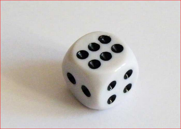
上面几篇文章介绍的都是虚拟的电子骰子,这篇文章将会介绍用Arduino来玩实体的骰子。相比前面几篇材料更复杂,牵涉到的配备更多。当然,所有的技术问题都能找到合理的解释,暂时无法回答的问题是“这个东西能干什么?”
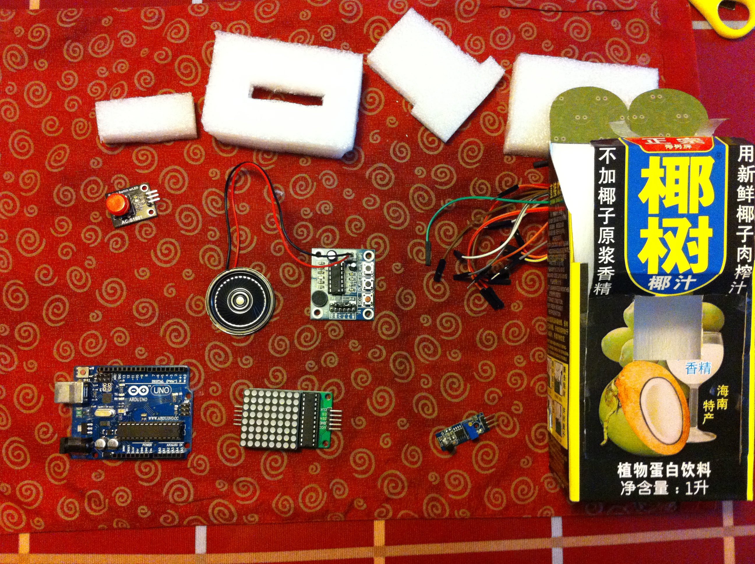
首先介绍使用到的材料:
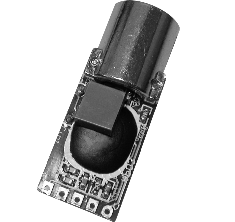
1. 电动骰子机(toabao购买,电池驱动,上面有个按钮,按动时自动旋转骰子)
2. 继电器 (我们用它来控制上面骰子机的开关)
3. 电池夹(用来给骰子机供电)
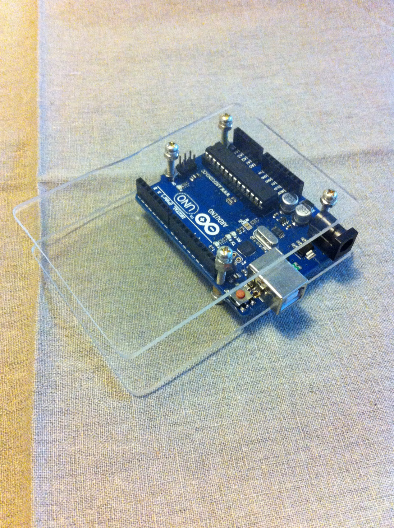
4. Arduino UNO (最基础的型号足够用的,如果你有其他的型号肯定也没问题)
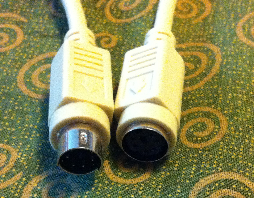
5. 摄像头 (我选用的是 罗技的 U-VQN42,这是很老的型号,以至于目前没有Win7的驱动)
6. 电脑 (我们用摄像头采集图像,然后使用Intel 的OpenCV来进行图像的识别处理)
可以看出这个实验涉及到的内容远远比之前的复杂,设计这个实验大约花费了2周左右,实做将近两天。
从流程上来说,功能过程如下:
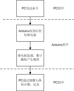
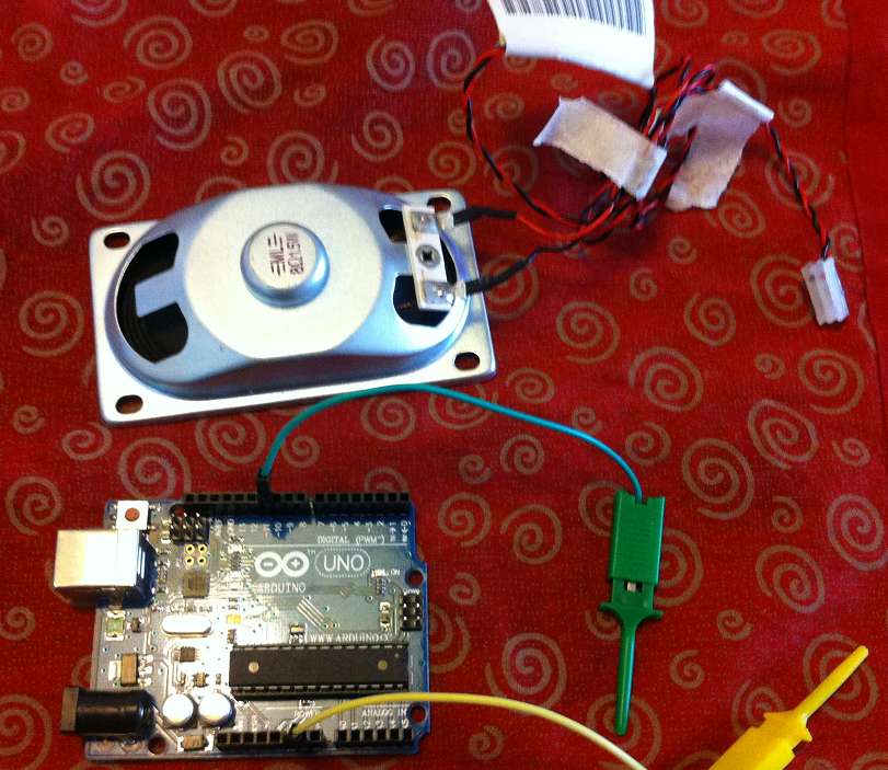
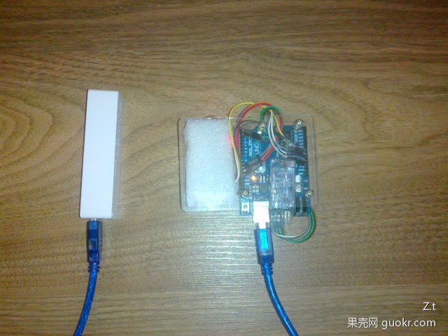
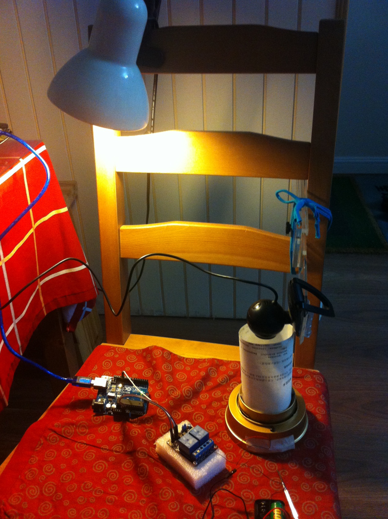
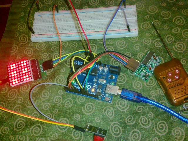
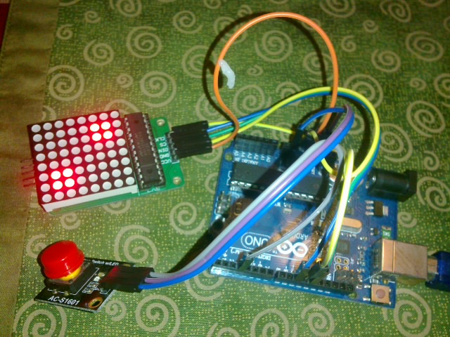
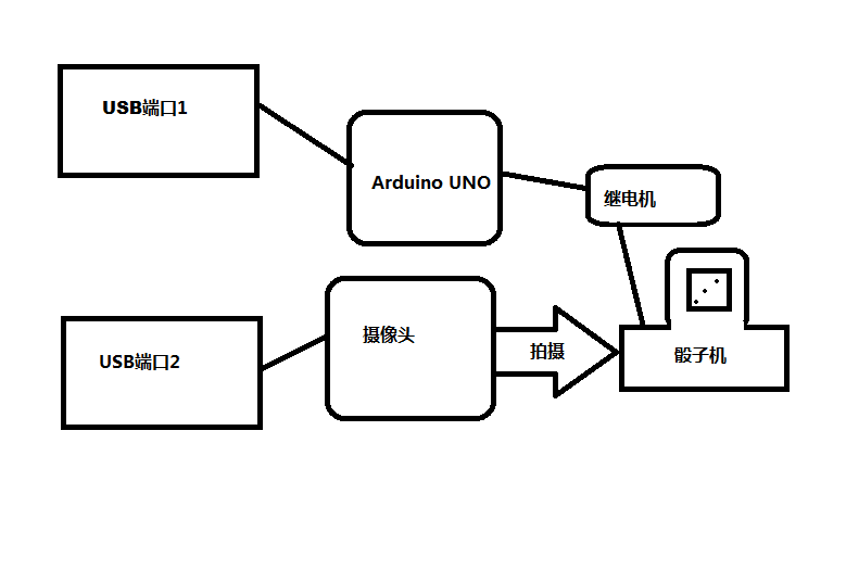
硬件部分的介绍:
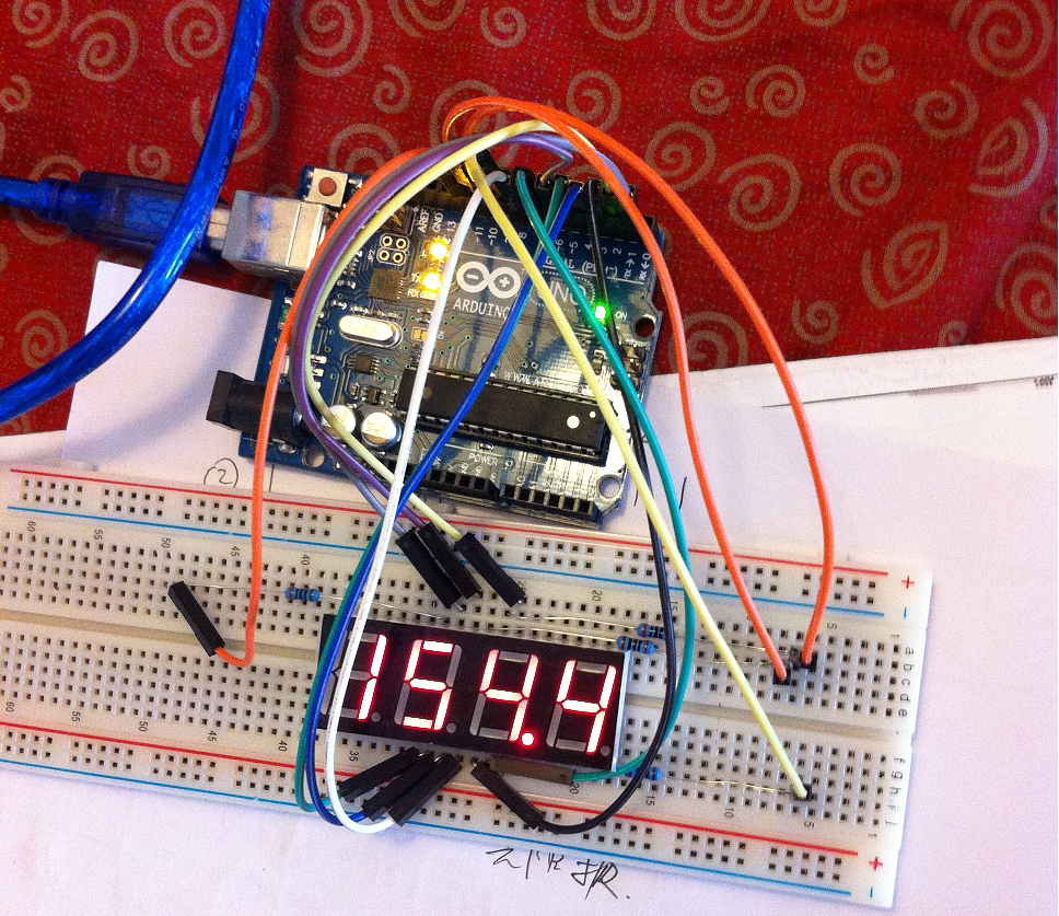
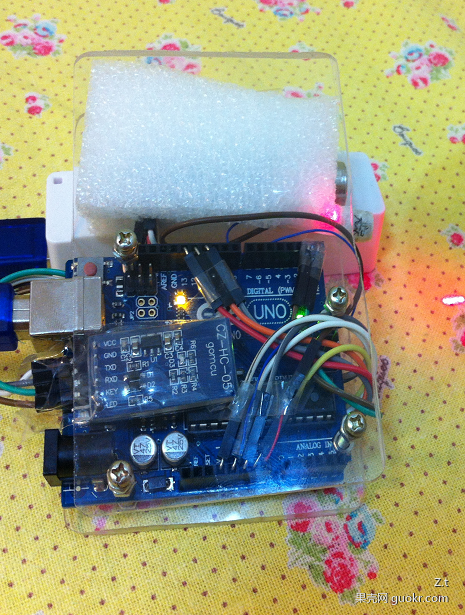
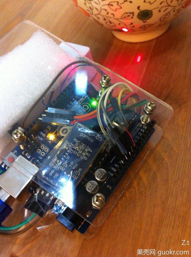
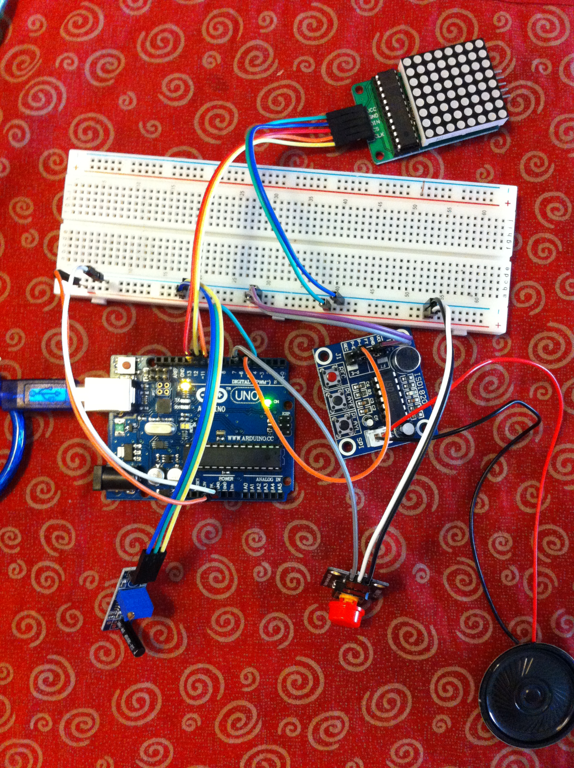
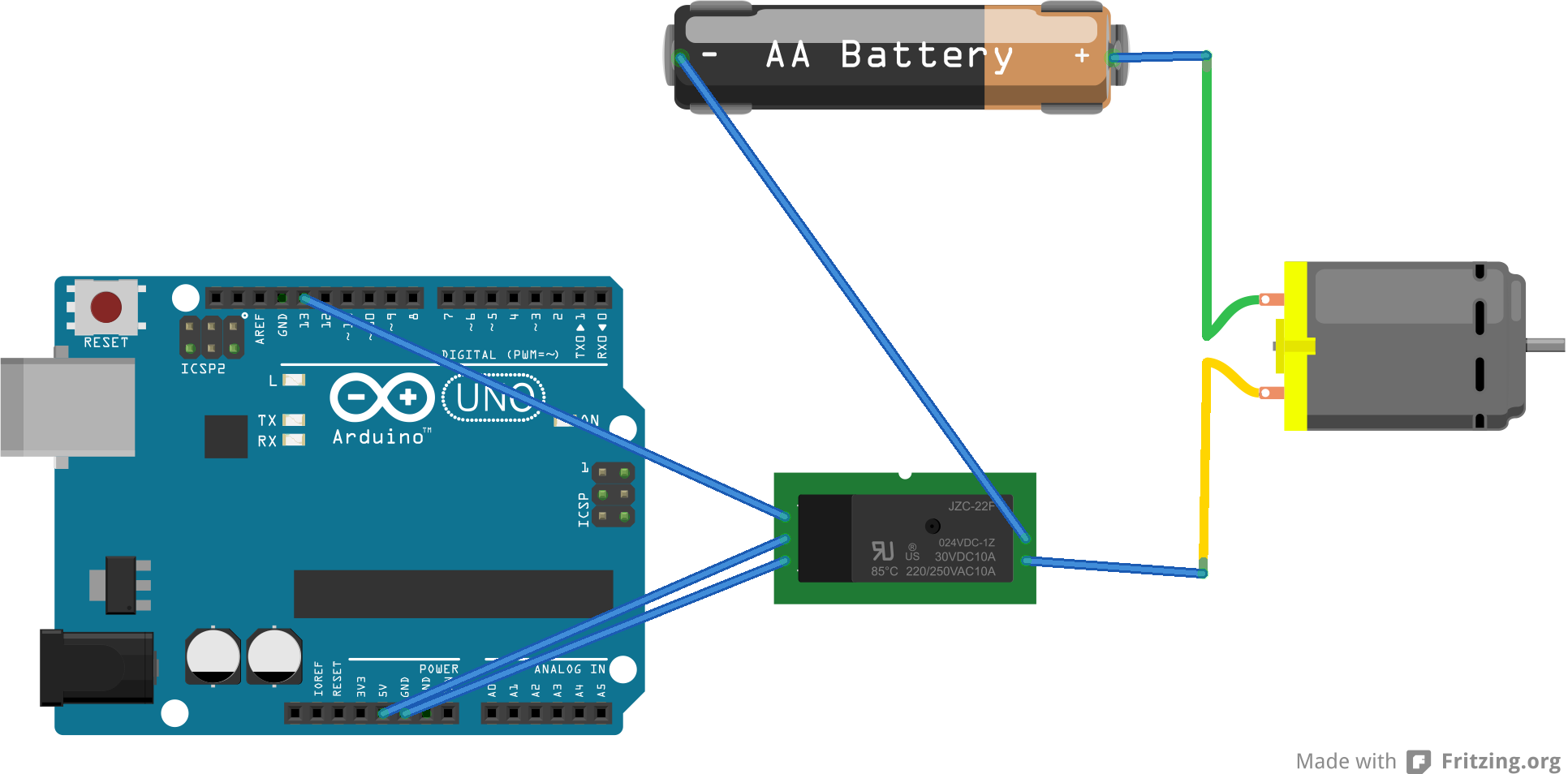
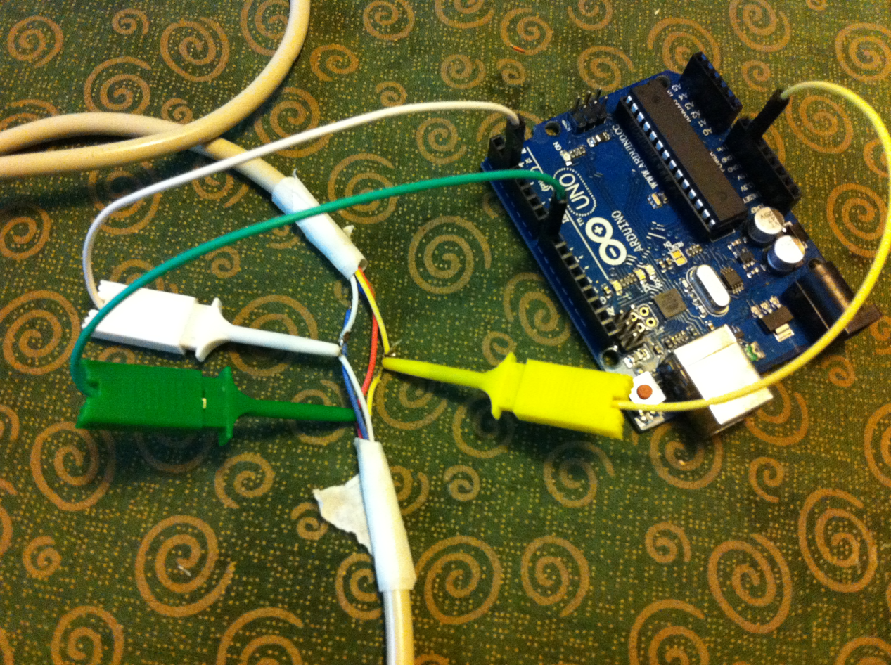
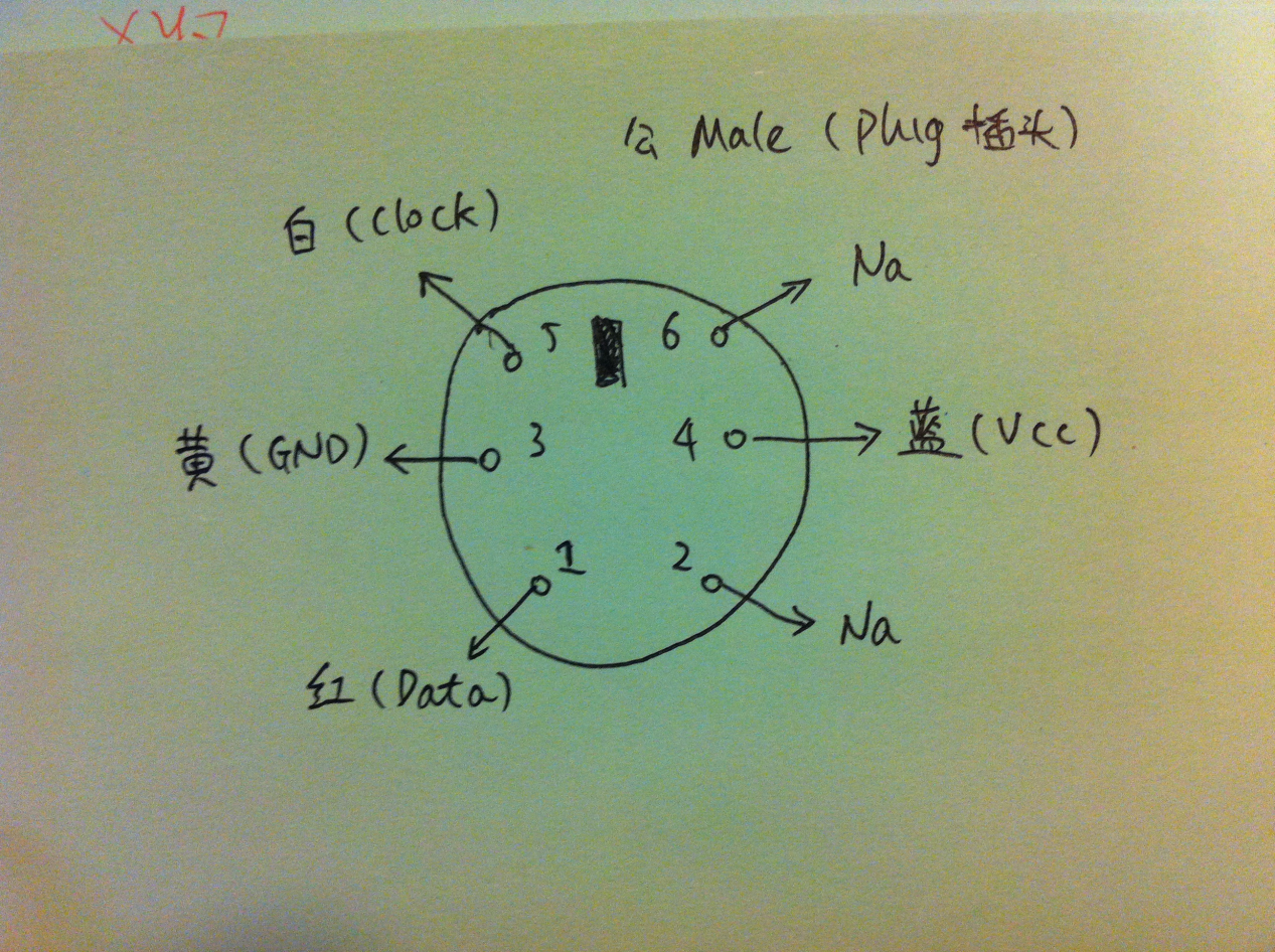
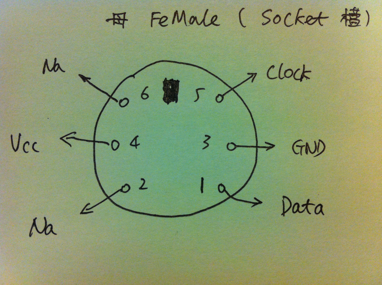
介绍Arduino的连接:

虽然骰子机内部是要安装2节电池的,但是我发现我用一节五号充电电池也能让它工作的很好,考虑到外壳强度的问题,也就直接选择一节电池了。Arduino在这里就是发挥骰子机开关的功能。
此外的建议是:连接继电器的常断开端口,这样,当断电时骰子机不会转动。
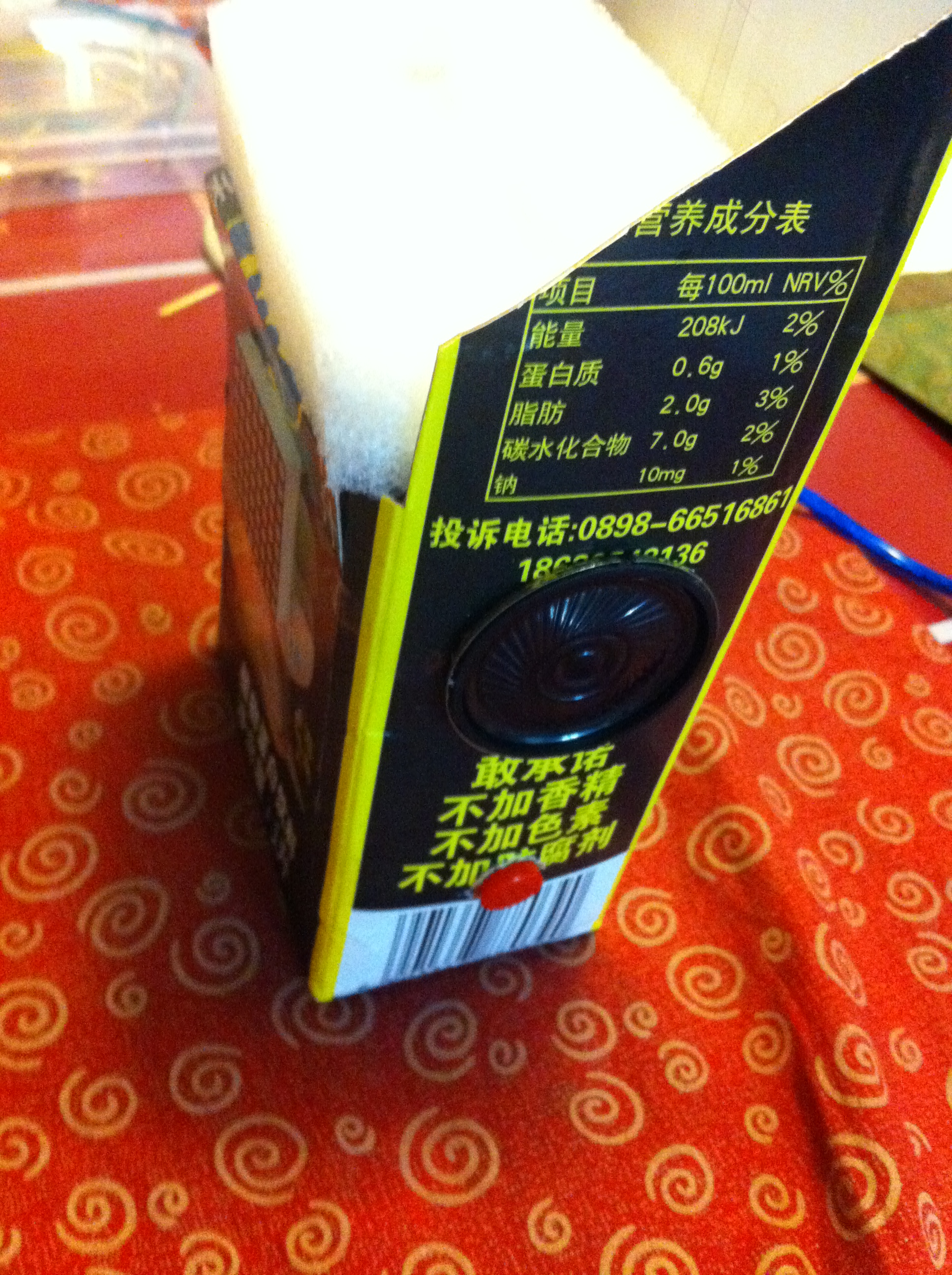
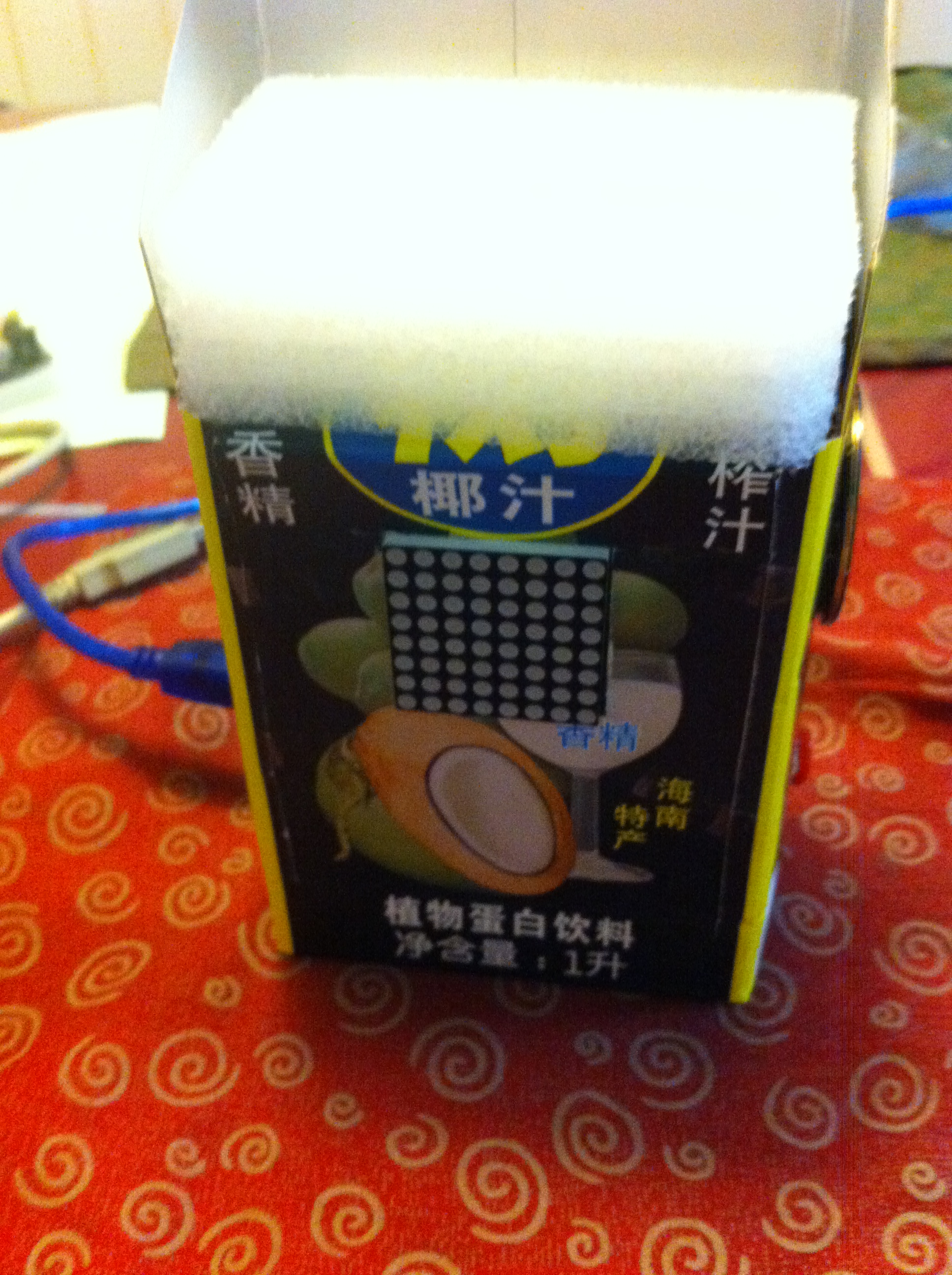
骰子机原来的是亚克力外壳,因为反光的问题,在测试时结果不理想,所以重新用纸做了一个。这里特别感谢严小姐,她用灵巧的双手帮我完成了这个工作。可以看到,目前整个摄像头可以伸进去,视界中只有地盘和白色的区域,这对于识别是非常有利的。还建议使用一个外部固定光源来进行补光之类的设定。

软件部分:
1. Arduino程序。
#define LED_PIN 13
void setup()
{
Serial.begin(9600);
pinMode(LED_PIN, OUTPUT);
//Default
digitalWrite(LED_PIN, HIGH);
}
void loop()
{
char c;
while (Serial.available() > 0)
{
c=Serial.read();
if (‘b’==c)
{
digitalWrite(LED_PIN, LOW);
}
if (‘s’==c)
{
digitalWrite(LED_PIN, HIGH);
}
}
}
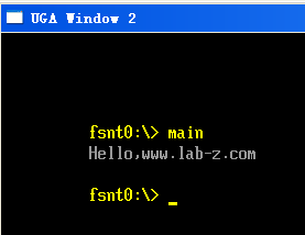
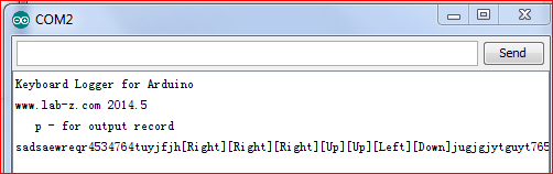
实验中 Arduino 的程序非常简单,测试时可以使用 Putty 这样的工具打开对应串口,直接发送命令测试。
2. PC端程序。
因为要使用OpenCV,所以选择了VS2008,本打算使用Delphi,无奈他的OpenCV不成熟。
这个程序可能分成两部分,一部分是串口通讯,只需要发送部分【参考1】,另外一部分是OpenCV的识别。算法上来自【参考2】,他给出了一种非常简单的算法:首先对图像进行Canny边缘提取,然后使用FloodFill对于包络范围进行填充,同时会返回填充区域的面积,利用面积就可以判断识别出来的是否为骰子的点(例如:1点的时候面积可能在200左右,2点的话,每个点可能在50左右),对于处在合理面积中的识别区域就判断为点数。
#include “stdafx.h”
#include <opencv2/opencv.hpp>
#include <opencv/cv.h>
#include <opencv/cxcore.h>
#include “opencv2/highgui/highgui.hpp”
#include
using namespace cv;
int p1=49, p2=258; //Paramters for Canny
Mat framepic; //framepic 存放摄像头抓取图像
Mat framegray; // framepic 灰度化后的图像
Mat canny; //canny 存放摄像头处理后的图像
VideoCapture cap(0);
int count[7]={0,0,0,0,0,0,0};
int counter=0;
int retry=0;
void on_trackbar(int, void*) {
Canny(framegray, canny, p1, p2);
imshow(“canny”, canny);
}
void delayshow(int dSecond){
time_t sTime=time(NULL);
while (difftime(time(NULL),sTime)<dSecond)
{
cap>>framepic;
cvtColor(framepic,framegray, CV_BGR2GRAY);
GaussianBlur(framegray, framegray,Size(7,7),1.5,1.5);
Canny(framegray, canny, p1, p2);
imshow(“canny”, framegray);
imshow(“Preview”,canny);
int c=waitKey(33);
if(c==27) break;
}
}
int main(int argc, const char** argv)
{
//==============================================
//code for COM port communication Begin
//==============================================
DCB dcb;
HANDLE hCom;
BOOL fSuccess;
TCHAR SPort[]=L”\\\\.\\COM7″;
char txcharstart[]=”b”; //b char for Start shaking dice
char txcharstop []=”s”; //s char for Stop shaking dice
DWORD iBytesWritten;
//Prepare COM part communication
hCom = CreateFile(SPort,
GENERIC_WRITE,
0, // must be opened with exclusive-access
NULL, // no security attributes
OPEN_EXISTING, // must use OPEN_EXISTING
0, // not overlapped I/O
NULL // hTemplate must be NULL for comm devices
);
if (hCom == INVALID_HANDLE_VALUE)
{
// Handle the error.
printf (“[Error] CreateFile failed with error %d.\n”, GetLastError());
return (1);
}
SetupComm(hCom, 32, 32);
// Build on the current configuration, and skip setting the size
// of the input and output buffers with SetupComm.
fSuccess = GetCommState(hCom, &dcb);
if (!fSuccess)
{
// Handle the error.
printf (“[Error] GetCommState failed with error %d.\n”, GetLastError());
return (2);
}
// Fill in DCB: 9600 bps, 8 data bits, no parity, and 1 stop bit.
dcb.BaudRate = CBR_9600; // set the baud rate
dcb.ByteSize = 8; // data size, xmit, and rcv
dcb.Parity = NOPARITY; // no parity bit
dcb.StopBits = ONESTOPBIT; // one stop bit
fSuccess = SetCommState(hCom, &dcb);
if (!fSuccess)
{
// Handle the error.
printf (“[Errror] SetCommState failed with error %d.\n”, GetLastError());
return (3);
}
//==============================================
//code for COM port communication End
//==============================================
srand(time(NULL));
int dTime;
if(!cap.isOpened())
return -1;
cap>>framepic;
cvtColor(framepic,framegray, CV_BGR2GRAY);
Canny(framegray, canny, p1, p2);
imshow(“canny”, framegray);
imshow(“Preview”, framegray);
//You may have to find the P1 and P2 value for your environment
createTrackbar(“p1″,”canny”,&p1,1000,on_trackbar);
createTrackbar(“p2″,”canny”,&p2,1000,on_trackbar);
//Loop shaking dice and count
for(;;)
{
//Shake start
printf (“[Message] Send start command \n”);
if (FALSE==WriteFile(hCom, &txcharstart, strlen(txcharstart), &iBytesWritten,NULL)) {
printf(“[Error]: %d”, GetLastError());
retry=0;
while ((TRUE==WriteFile(hCom, &txcharstart, strlen(txcharstart), &iBytesWritten,NULL)) ||
(retry>5))
{
printf(“[Error]: %d”, GetLastError());
retry++;
}
}
dTime=rand()%2+1;
//Shake the dice for a random seconds
printf(“Shake delay %d \n”,dTime);
delayshow(dTime);
//Shake stop
printf (“[Message] Send stop command \n”);
if (FALSE==WriteFile(hCom, &txcharstop, strlen(txcharstop), &iBytesWritten,NULL)) {
printf(“[Error]: %d”, GetLastError());
retry=0;
while ((TRUE==WriteFile(hCom, &txcharstop, strlen(txcharstop), &iBytesWritten,NULL)) ||
(retry>5))
{
printf(“[Error]: %d”, GetLastError());
retry++;
}
}
//It delay 5 seconds for dice stopping
delayshow(5);
//==============================================
//code dice point recognize start
//==============================================
cap>>framepic;
cvtColor(framepic,framegray, CV_BGR2GRAY);
GaussianBlur(framegray, framegray,Size(7,7),1.5,1.5);
Canny(framegray, canny, p1, p2);
imshow(“canny”, framegray);
imshow(“Preview”,canny);
int num = 0;
for(int y=0;y<canny.size().height;y++)
{
uchar *row = canny.ptr(y);
for(int x=0;x<canny.size().width;x++)
{
if(row[x] <= 128)
{
int area = floodFill(canny, Point(x,y), CV_RGB(0,0,160));
printf(“filling %d, %d gray, area is %d\n”, x, y, area);
if(area>37 && area < 300) num++;
}
}
}
printf(“number is %d\n”, num);
//==============================================
//code dice point recognize end
//==============================================
counter++;
count[num]++;
printf(“=====================================================\n”);
printf(“Total=%4d| One | Two | Three | Four | Five | Six |\n”,counter);
printf(” | %4d|%4d | %4d | %4d | %4d | %4d|\n”,count[1],count[2],count[3],count[4],count[5],count[6]);
printf(“=====================================================\n”);
printf(“Show result delay 3s\n”);
delayshow(3);
int c=waitKey(33);
if(c==27) break;
}
system(“PAUSE”);
CloseHandle(hCom);
return 0;
}
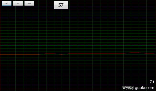
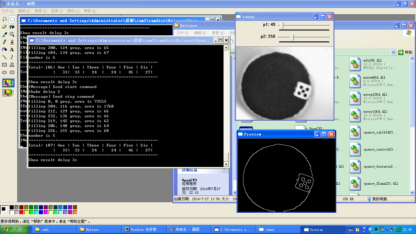
运行结果就是下面这个样子。Console 显示统计结果,旁边一个显示灰度化后的摄像头内容,另外一个显示边缘提取后的结果。

我只做了一个多小时,收集的结果不多,看起来结果并不平均,不知道如果做个一万次之类的会是什么结果。
运行时的视频(刚开始放在Tudou的时候,审核没有通过,估计是因为名称中有“骰子”。后来申诉了一下)
http://www.tudou.com/programs/view/TtqRy-KRr-8/?resourceId=414535982_06_02_99
其实更好的方案是记录下每次的运行结果,因为我发现这个东西每次之间似乎有相关性。比如说这次出现六点,那么下次出现六点的可能性似乎大于 1/6。猜测和骰子机的摇骰子方式有相关性。
最后的最后,吐槽一下电脑的问题:第一个没想到是前面说过的罗技摄像头居然不支持Windows 7,如果你也想做同样的实验需要购买摄像头不妨考虑一下买个二手的微软摄像头,只是外观差一些,效果和支持应该比罗技的好多了;第二个是梅捷 SY-D2700-U3M 的主板,BIOS中居然没有设计风扇温控功能【参考4 提到的Watchdog就是为他设计的】。最近天气热了,硬盘丢失的问题更是频频出现,鲁大师检测CPU温度50左右,主板温度在60左右就会出现这个现象。当我连接一个风扇到上面的时候,5000RPM让人难以忍受。下一个实验就是如何做一个能够调节转速的风扇了。
参考:
参考1:VS2008串口发送参考代码
http://www.lab-z.com/%E4%B8%87%E4%B8%87%E6%B2%A1%E6%83%B3%E5%88%B0%EF%BC%8C%E4%B8%B2%E5%8F%A3%E7%9A%84%E6%95%85%E4%BA%8B/
参考2:超简单的opencv骰子点数识别,效果居然还不错 http://chen-xiao.com/?p=250
参考3:OpenCV的imshow无法正常显示视频http://haibuo1981.iteye.com/blog/1401764
非常感谢作者解决了困惑我一下午的问题,如果你用 cap >> img 这样之后,想再通过显示imShow到屏幕上(特别是在一个循环中),必须使用waitKey(xx)给程序足够的时间来更新画面。
参考4:使用 Arduino 打造一个硬件的Watchdog
http://www.lab-z.com/%E4%BD%BF%E7%94%A8-arduino-%E6%89%93%E9%80%A0%E4%B8%80%E4%B8%AA%E7%A1%AC%E4%BB%B6%E7%9A%84watchdog/